|
Henry Ford had overwhelming success with the four cylinder Fords built during the 1906 – 1908 model years, with close to 14,000 sold (all models, all years) in Model N, Model R and Model S (or SR). With Ford the #1 automobile maker in the world, his next car was expected to be a good one. No one could have predicted just how successful it would become!
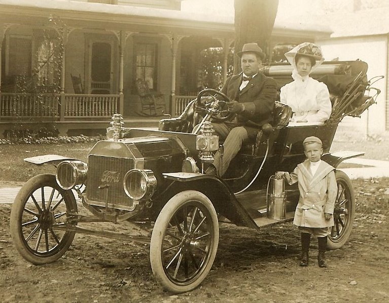
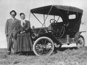
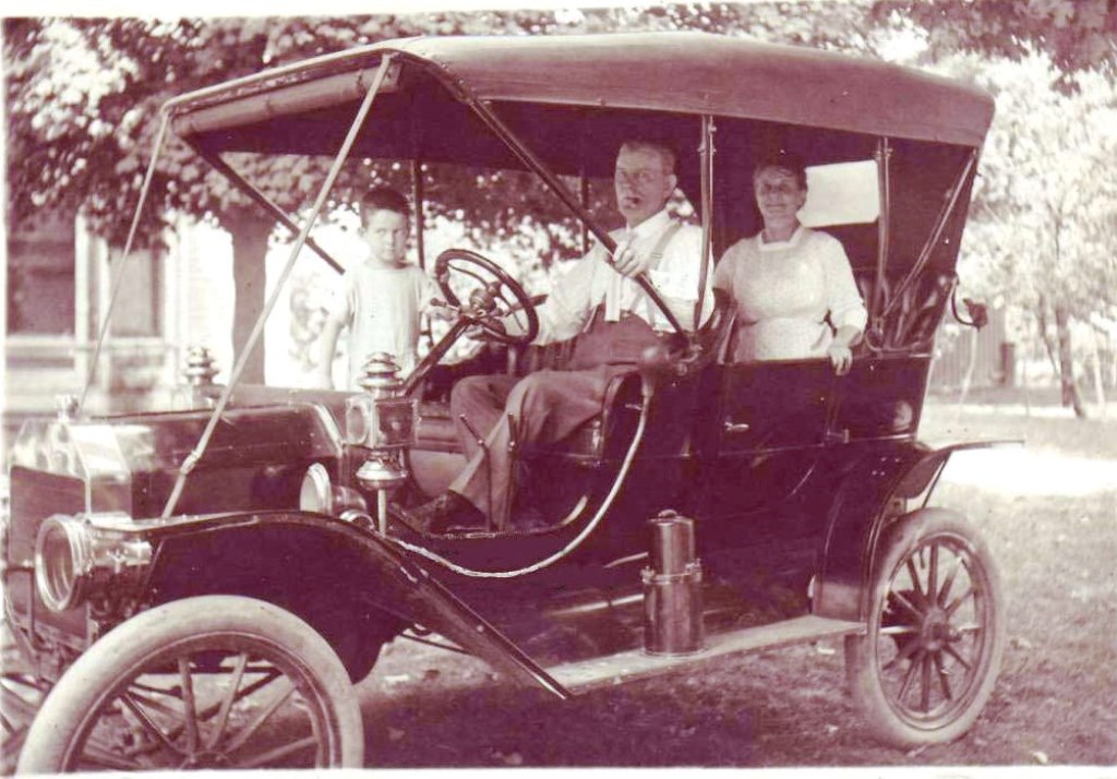
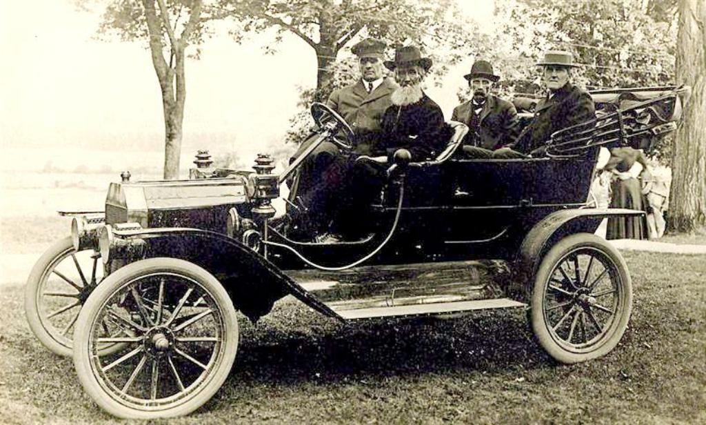
A happy family with their very early 1909 Model T.
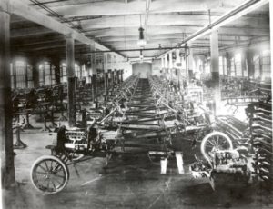
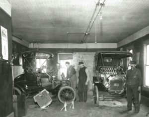
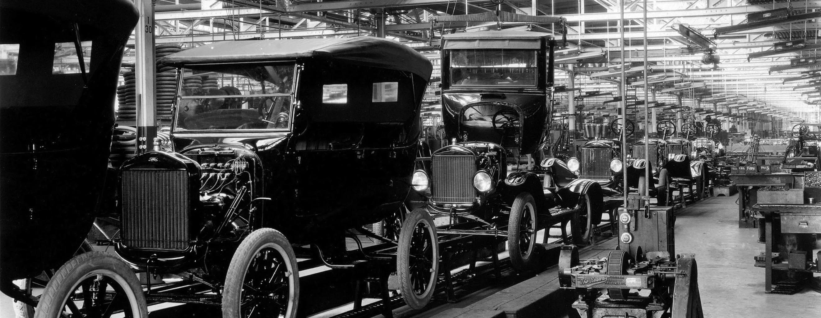
Piquette assembly plant showing brand new Model N Fords being built
Ford had a relatively new state of the art assembly plant on Piquette Avenue in Detroit. It had many features that made it efficient for automobile production including designated work stations, an elevator capable of carrying cars between floors, and even a built – in 2500 gallon fire suppression system on the roof.
By late 1907 Ford knew that there were many improvements that could be made to increase sales. In particular, the Models N and R were built only as two seaters. The Model S / SR saw a limited number of touring and town car bodies built. Ford was the leader in car sales world wide. He planned carefully for the launch of his new model, scheduled for 1909 model year.
To improve the design concept and to limit outside interference Ford had a “experimental room” walled off in one corner of the plant. Inside the experimental room only a few key employees were allowed to work full time, and fewer others were allowed to peek inside at the progress. The key employees who worked in the experimental room were engineer / draftsmen Joseph Galamb, Jules Hartenberger, Charles Balough, and Eugene Farkas. Henry Ford’s right hand man and fairly competent metallurgist / tool maker Childe Harold Wills ( he hated the name Childe and always signed his name C. Harold) was regularly in the room, and C.J Smith who fabricated parts for the new Ford.
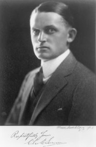
 Joseph Galamb, draftsman and designer of some of the earliest Model T parts. Joseph Galamb, draftsman and designer of some of the earliest Model T parts.
Equipment inside the third floor experimental room included a few drafting tables, a lathe, mill and other miscellaneous machine tools that ran off a line shaft mounted to the ceiling. There were two large black boards, and a small rocking chair for Henry Ford. The design team of Galamb, Farkas, Balough and Hartenberger were all Hungarian immigrants who frequently discussed the project in their home language. Galamb claimed that some calculations were done in metric and later converted to US measurement standards. Henry Ford was impressed by the group, and apparently did not mind them operating in their native tongue. In fact he is known to have said things like “let’s hear some of that dago talk and get some work done” when he thought they were not moving fast enough!. In any case their efforts revolutionized the car, and the results speak for themselves today.
The design of the Model T Ford was intended to meet several goals, the end result, of course , was to make the Ford Motor Company lots of money. At this time Ford Motor Company was primarily an auto assembler, not a manufacturer. The Model T design had to be easy to manufacture and assemble, since Ford would be purchasing the majority of the parts from outside manufacturers. Keeping the cost of manufacturing low would ensure that the price of parts and subassemblies was low, which would increase profits. Low cost to build the car meant that the purchase price could be lowered, which would increase the number of potential customers. More potential customers meant increased production volume. All of these factors fed upon themselves to constantly lower the cost of a Model T Ford over its entire production run.
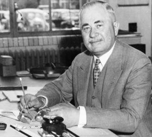
Another key employee involved in the earliest development of the Model T was Charles Sorensen, a big tall Danish fellow who was chief pattern maker. The Model T used many parts made from cast iron including wheel hubs, engine major components, and much of the transmission. None of these parts were cast by Ford Motor Company, but Ford designed them and also designed the tooling to make the parts. Sorensen was very good at making casting patterns that worked well at the foundry, yielding few failed parts and easy machining processes. It is hard to overstate the importance of this; and it was often Sorensen who would go back to the design team in the experimental room to advise them a way to simplify a part to make it easier to produce. Sorensen personally went to the foundries to supervise casting, and worked with machine shops like Dodge Brothers to ensure the final product was high quality and inexpensive.
By 1913 Charles Sorensen was the #2 man at Ford Motor Company. He autographed this photo that year. Eventually by the early 1930’s he became the #1 employee in charge of the entire company, under the Ford family of course.
Another frequent visitor to the experimental room was Edward S “Spider” Huff. Huff had been friends with Henry Ford since before Ford built his first car, the Quadricycle, in 1896. Huff’s contribution to the Model T Ford was its most iconic and unique feature, the completely contained “low tension magneto” built in to the engine.
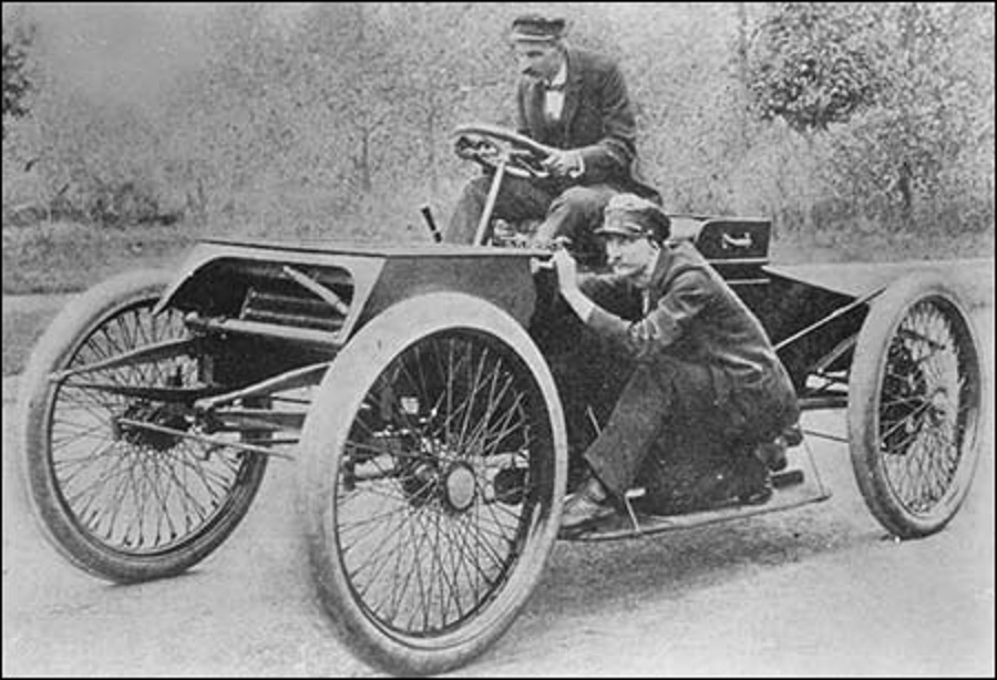
Spider Huff recreating the position he used on Ford’s 1901 race car. He pumped the fuel pump while Henry steered!
While Ford called it a “low tension magneto” electrical engineers of today would call it a variable frequency variable voltage permanent magnet alternator. Huff called his device a “Low Tension Magneto” because unlike the high tension magnetos of the day, Huff’s device provided AC (Alternating Current) voltage to power an individual temblor type spark coil for each cylinder. These temblor coils were common in those days, nearly every gasoline powered car used them with a DC (Direct Current) storage battery as an ignition power source.
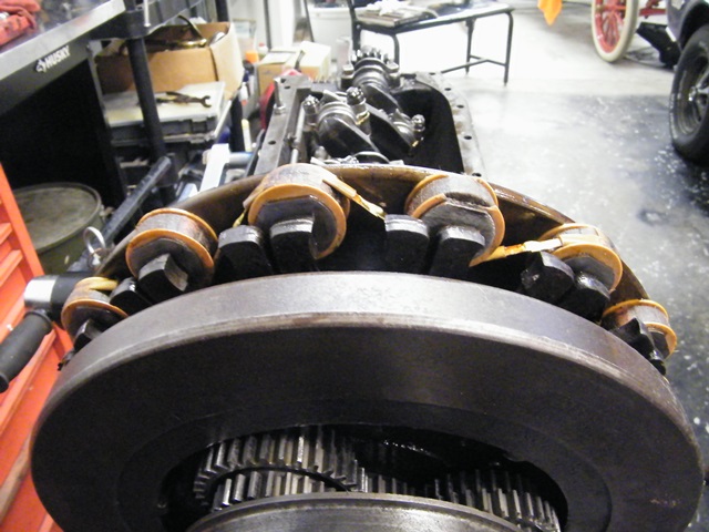
The earliest Huff designed Model T magneto has magnets that spin with the flywheel while the round shaped field coils stay stationary.
Huff’s new device was extraordinary on many levels. First, it completely eliminated the need for a battery. The Model T magneto easily provided a hot spark at cranking speeds. Output of the Ford / Huff magneto ranges from about 6 volts at cranking speed to nearly 30 volts at maximum engine speed. Even more revolutionary is the fact that the Huff magneto provides a spark event that is synchronized to the piston position. It enables each of the four temblor coils to provide spark at exactly the correct time , much more accurate than any other ignition method of the day.
The Model T Ford engine combined all of the latest advancements in one tour – de – force automotive design. The cylinder head was a separate, removable part which allowed maintenance of the valves and pistons without removing the engine from the car. The crank case had all four cylinders cast as one unit, thanks to “Cast Iron Charlie” Sorensen’s ingenious pattern making techniques. The engine and transmission were entirely encased in one long “engine pan” that included the mounting positions that attached the unit to the frame and kept dirt and water out, while keeping lubrication in. This was a major advance from previous Ford designs where the transmission was exposed and needed to be greased every few hundred miles. Earlier Ford engines operated on a “total loss” oiling system where oil from a tank dripped into the main bearings and was slung on the piston walls before falling on the ground under the car.
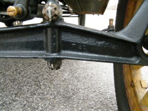
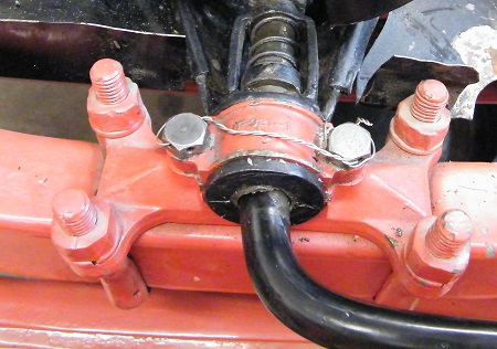
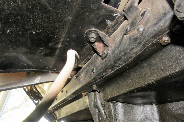
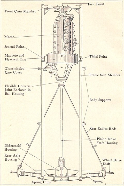
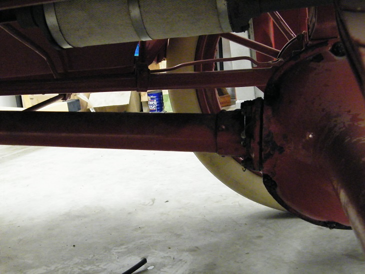
Another breakthrough in design was the Model T’s “three point” mounting of important components. This included the engine / transmission unit, the front axle, and the rear axle. Previous Ford designs had big problems with brken crank cases due to the rough roads of the day and the tendency of cars to twist and vibrate while driving down the road. The Model T incorporated solid mounting of the engine pan arms on two axis to prevent cracking, yet the nose of the engine pan was mounted in a bearing. This allows the frame to flex without causing breakage of the engine pan or crank case.
The Model T engine has a displacement of 177 cubic inches. Pistons were cast iron with four piston rings, the lowest ring below the piston pin. The crankshaft and connecting rods were forged steel. Rated power is 20 – 22 horsepower which seems low to us today. In fact the Model T Ford is very adequately powered given the car’s light weight and its operating environment of dirt roads.
The first approximately 2499 Model T engines had a water pump integral with the engine. As such we collectors and restorers call cars equipped with these engines “pre – 2500” Model T’s. They are a sort of production prototype that led to a major redesign of the engine for serial numbers 2500 and later.
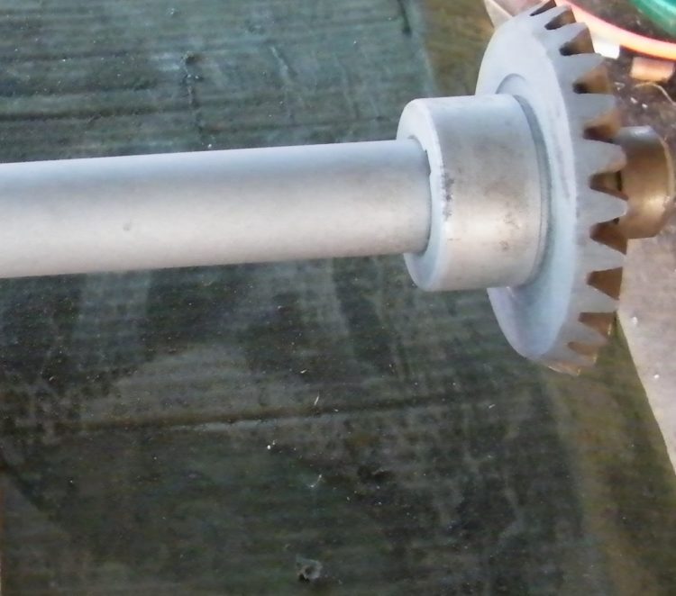
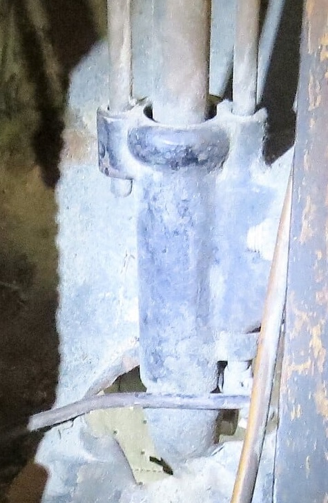
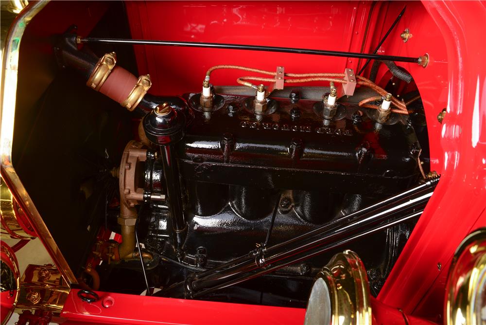
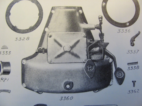
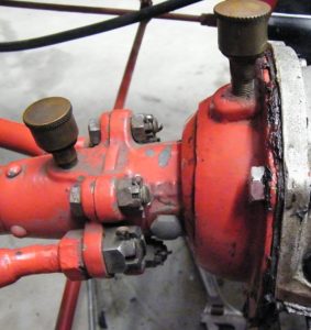
The water pump was driven by a shaft connected to a water pump drive gear inside the front engine cover.
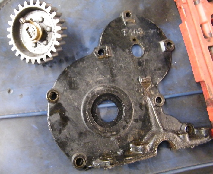
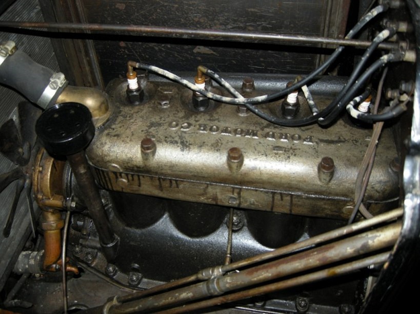
The water pump drive gear is meshed with the camshaft gear. Here is a look at the pre – 2500 engine block showing where the water pump drive gear lives:
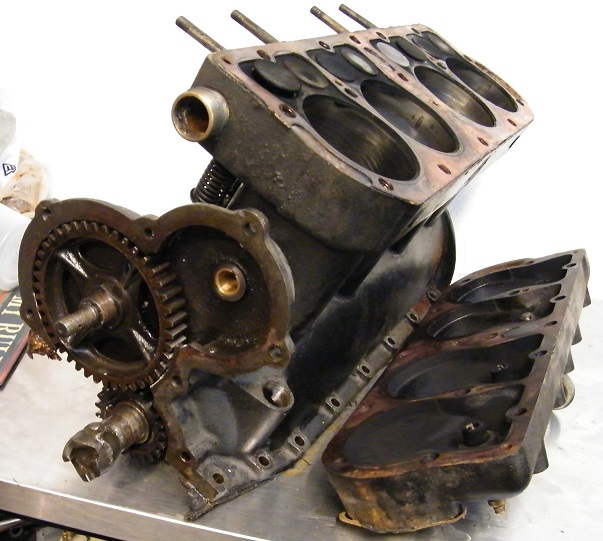
The engine block, cylinder head, and crank ratchet assembly are also unique to the first 2499 cars. We can see in the image above that the crank ratchet female “hook” is riveted to the crankshaft. The cylinder head has its water outlet opening on top of the head, and the water inlet is on the front of the engine block.
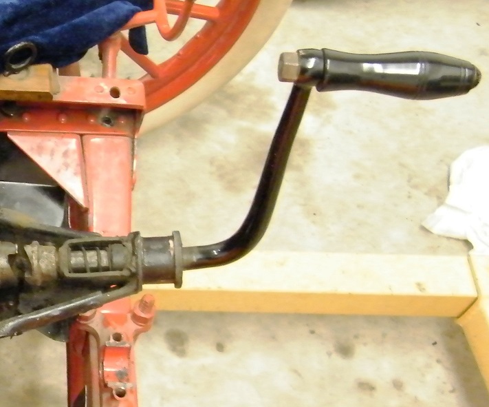
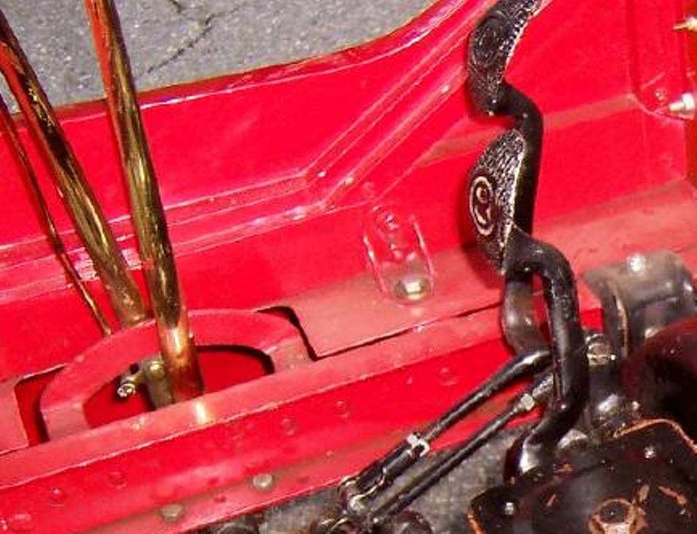
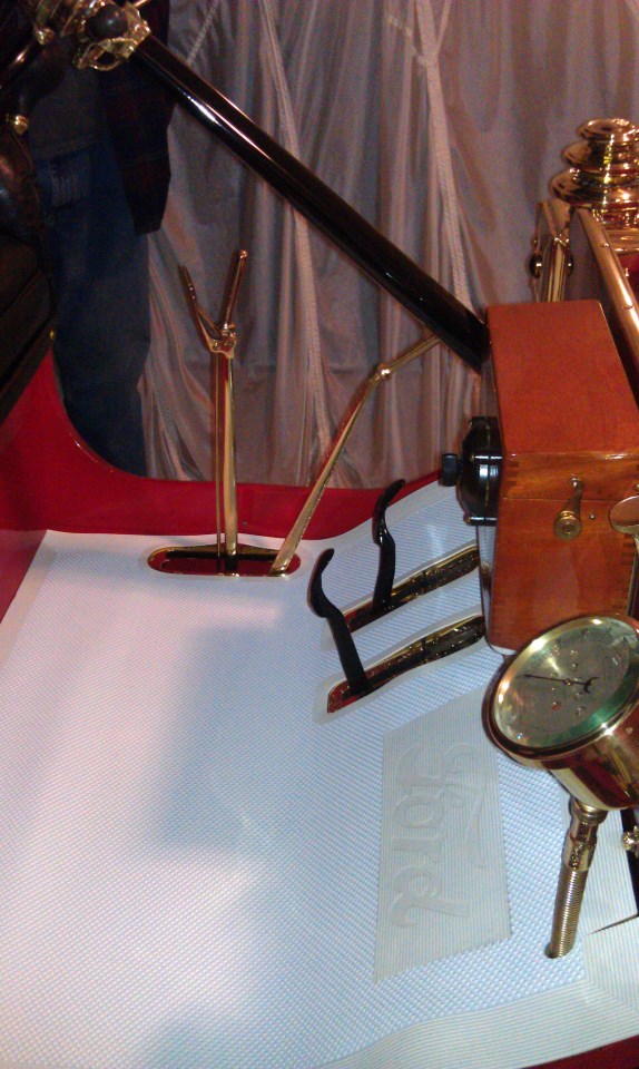
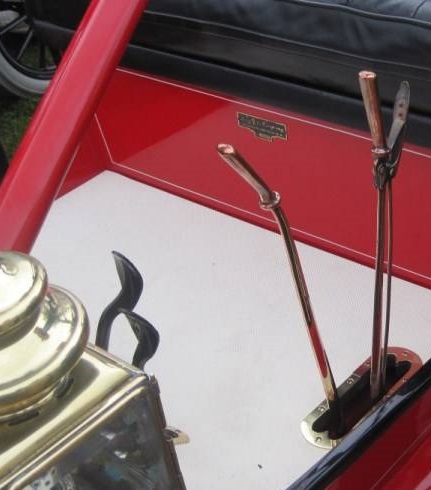
The crank ratchet is completely unlike later Model T’s. The crank handle would have been brass plated originally. Note that the crank handle when not in use can be stored locked up or down, the spring forces the crank forward against a lock stop mechanism.
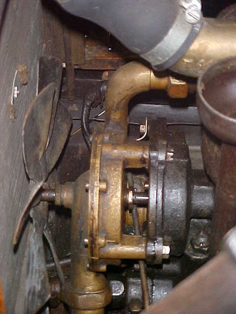
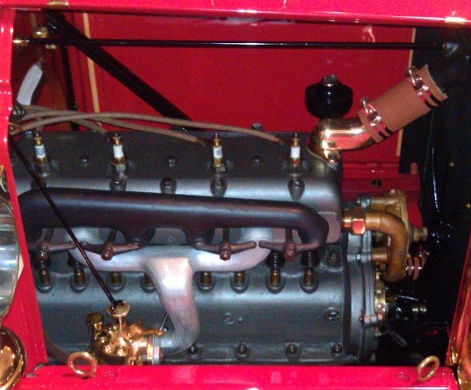
Back to the water pump – in theory this was an improvement over the NRS Fords which had a water pump mounted in the bottom of the radiator. In practice it did not function too well. There are three places on the water pump shaft notorious for leaks. Oil leaks from the place where the water pump drive shaft passes through the engine front cover. Water leaks from both ends of the water pump where there are asbestos crush seals riding on the shaft. It all ends up making a biig mess of the engine compartment. The timer, being mounted slightly to the right and below the water pump is constantly being doused with water droplets. The water pump inlet is a brass elbow with a crush seal where the elbow connects to the water pump. Meanwhile the other end of the water pump attaches to the front of the engine block with yet another crush seal. All of these crush seals tend to drip a bit. Not good.
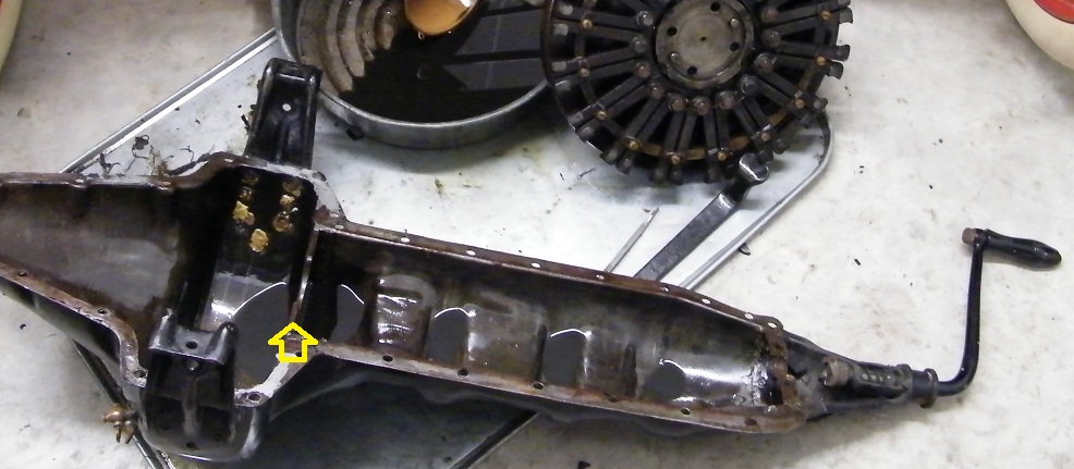
Arrow points at the engine oil pan “dam” behind the #3 main bearing found on the earliest Model T’s.
The engine pan was a manufacturing and design success. The pre – 2500 cars had an engine pan that had no access door in the bottom. Ford would not figure out that was a necessary thing until well into 1911 model year production. Also, the earliest Model T’s have a “dam” that keeps oil in the forward part of the crankcase quite deep, it has an overflow hole about 4″ from the bottom. This made the early engines leak a lot of oil and burn a lot of oil, as Henry Ford himself was about to discover.
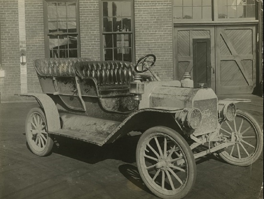
This is the earliest known Model T photograph, taken in the courtyard adjacent to the Piquette Avenue Ford Assembly Plant in the summer of 1908. This car has been branded “T #1” by Dr. Trent Boggess, and we think the title is appropriate. While this car is not likely to be serial number 1, it is certainly the first T to be photographed, and very significant in that Henry took it on a hunting trip to Iron Mountain, Michigan in 1908. According to the account in “Tin Lizzie” by Philip van Doren Stern, the drive was 1357 miles round trip. The Ford used 68 gallons of gasoline for an average MPG of 19.95 MPG. Not too bad, but the oil consumption is listed as 11.5 GALLONS OF OIL. Needless to say there was room for improvement.
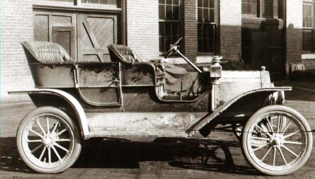
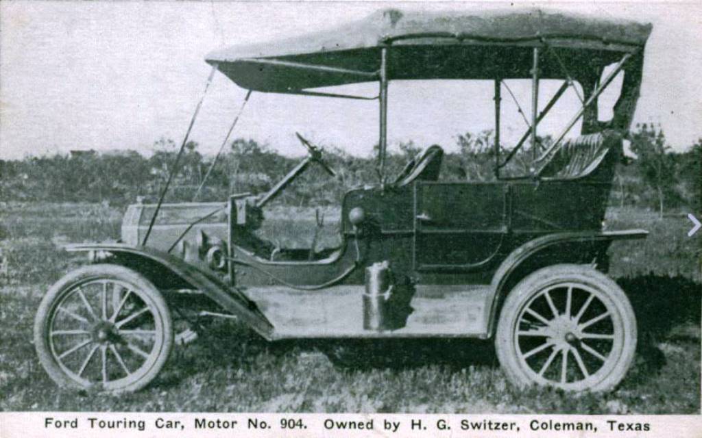
Side view shows typical features of the first 2499 Model T’s – flat front fenders, two pedals, two levers. This car is not equipped with a top, however top irons are standard and you can see them poking out from the front and rear seat. The car is equipped with Atwood Castle Lamps. Notice the position of the door handle, much lower than seen on later 1909 production.
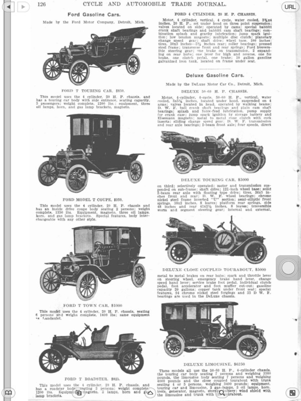
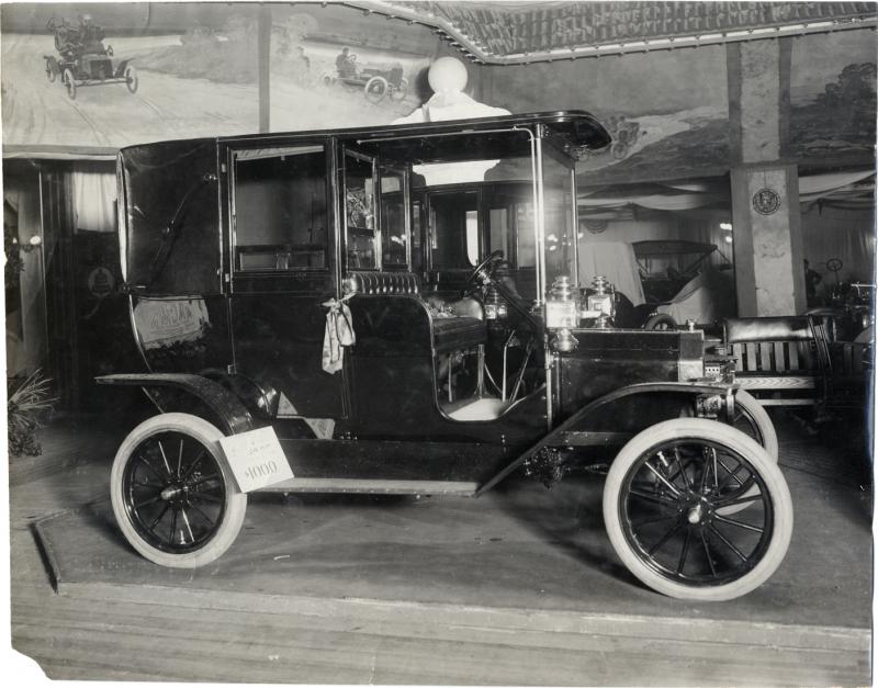
Upon its announcement the Model T was to be produced in several body styles including the Touring, Coupe, Landaulet, Town Car, and Roadster. Kerosene cowl lamps and tail light were standard across the product line.
A very early 1909 Model T Ford. Notice the low position of the door handle, E&J three tier side lamps, E & J headlamps and carbide generator, square front fenders, and typical “American” top. The horn is a double twist Rubes or Non Pariel. The car has two levers and two pedals, typical of serial numbers below 900.
Headlamps and top were optional on the 1909 Fords. Windshields were also optional at extra cost. Other options available from the factory were Weed brand tire chains, speedometers, and a Prestolite carbide tank to replace the carbide generator.
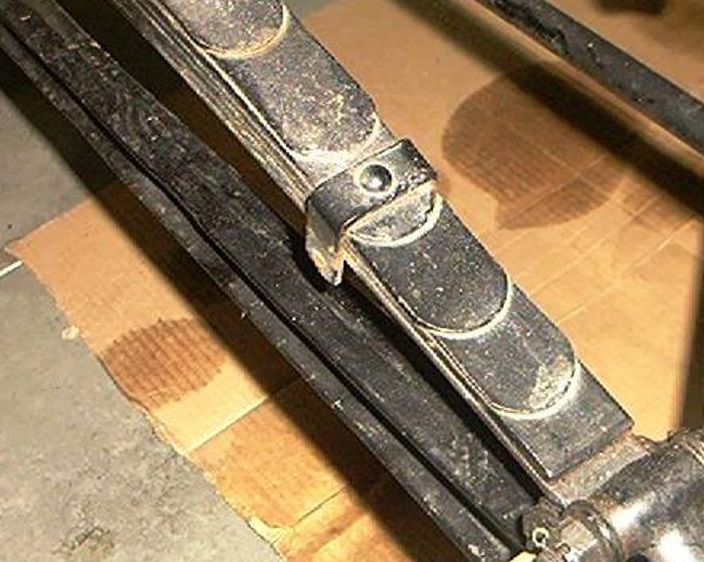
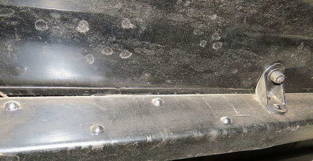
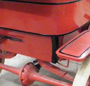
Running boards on the early 1909 Model T’s were made from lumber, covered on the top side by battleship grey linoleum trimmed on the side with brass. The brass trim was secured to the lumber by a row of screws.
The front fenders on the 1909’s made until about May 1909 were flat on the front with no “bill” as seen on later front fenders. The door handles on touring rear doors are much lower than seen on later cars. Horns are sourced from several makers including Non Pariel, Rubes, and Dragon.
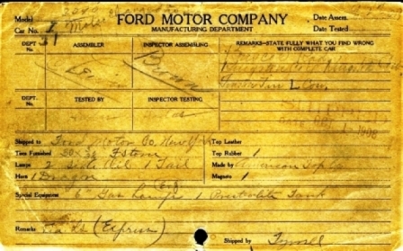
The build sheet from Model T #1. The engine was replaced with #31 prior to shipment. The car was shipped to New York for export to England. Note the headlamps are “E&J 6” and the horn is “Dragon” while the top is made by “American”.
|

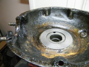
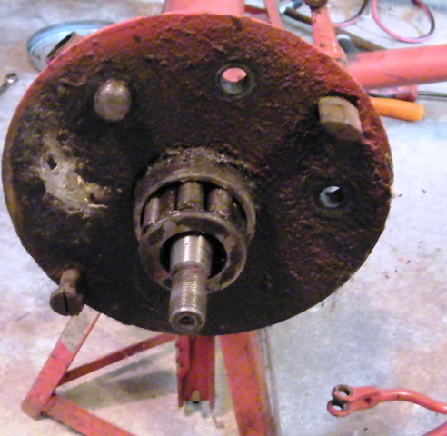
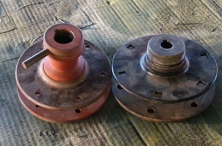
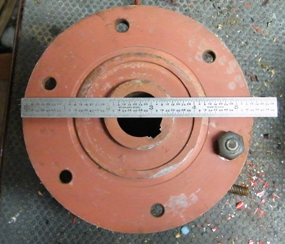
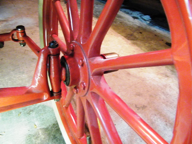
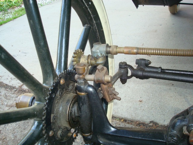
 The outer backing plate on the rear axle provides a place to mount the brake shoe, attach point for the radius rod, and the brake actuating cam at the top. In 1909 this plate was flat and plain on both sides. Not that this photo shows a later tapered axle. The early cars did use a Hyatt roller bearing at the outboard ends of the axle.