|
Getting old Lizzie
going is one thing, getting her stopped is another! These Rocky
Mountain brakes are almost a must when you have a Ruckstell or
overdrive. Hooks up to the regular brake pedal, and uses the
rear wheels to stop instead of the transmission.
  The installation instructions
can be downloaded
here.
The installation instructions
can be downloaded
here.
Be sure to read
the differences between the two types
here.
Click here to jump
straight to the step
by step guide.
DISCLAIMER:
First let us state that the images and descriptions shown here
do not preclude reading and understanding all the directions
that come with the Rocky Mountain Brake kit. You, and you alone
are responsible for the installation of anything on your 90+
year old car. Please read the instructions that come with the
kit. We share this information to aid in your understanding. By
no means is this information intended to solely instruct the car
owner or mechanic to install this system.
1926
-1927 installation also ?t? trucks
Correct rear axle for the above years has an 11? brake drum and
housing (ex- ception being ?t? ?t? truck worm drive) and do not
interchange with the 1909- 25 8? rear axle assembly. Hassler
shocks can not be used with the additional brakes. Before
starting, check to see if the stock drum is close to the backing
plate. Any large gap here (too many shims, incorrect parts) will
show up later as brake bands will not line up on drums. This
assembly is designed for ?t?s as ford manufactured. Any modified
frames, as with speedsters, you will have to make your own
alterations. Start by removing rear wheels.
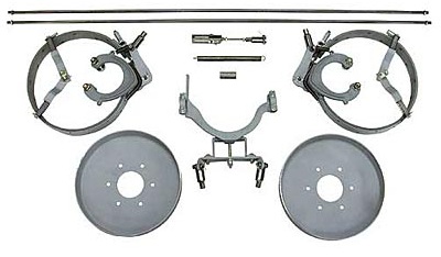
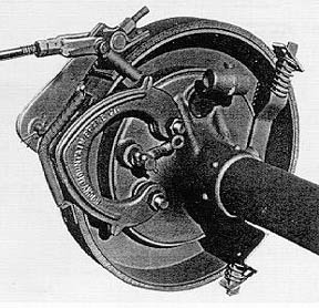
Brake assembly installation
Bands are tagged left side up-right side up (left side is
drivers side -u.s.a.). Start by removing the 2 bolts from radius
rods. Using bolts supplied, place the front bolts thru the wheel
side of the backing plate and radius rod, keep- ing radius rods
in same location against backing plate. Do not attempt to place
casting between backing plate and radius rods! The 2 rear most
1/4? riv- ets must be removed for the rear support brackets
using 1/4? bolts supplied (not required on ?t? ?t? one 5/8?
bolt) .now place casting and band assembly onto bolts. The rear
spring brackets, the shortest goes on first to the top, then the
longer faces to the bottom. Leave final nuts off these for now
(?t? ?t? brackets are installed as assembled). Place wheel on
axle without axle key. Run nut up to hub and slip cotter pin in
place. This way you may spin wheel without turning the whole
gear assembly. Check for any parts that may be dragging against
drum because of worn axle surfaces or hubs caused by bro- ken
axle keys. Over time, wheels may go on further than originally.
You may solve this by grinding face of offending part slightly
or add an axle shim. Install final nut on rear support brackets
and adjust top bracket so there is space between bracket and
band tab towards rear of car. Bottom bracket
Is adjusted with space between bracket and band tab towards
front of car. The reason for this is to allow band to travel
forward with the rotation of the wheels which is where the self
energizing feature is obtained.
Adjusting band
Run down the top major adjustment nut until lining is tight
against the drum. Now adjust the nuts that are below on the
threaded 6 1/2? bolt to give the spring about 1? in length. Back
off the top adjustment nut so the wheel now will spin freely
with approximately 20 thousands clearance. The band and lining
will conform after driven a few miles and should be re-adjusted
for a more precise adjustment, but allowing for drum expansion.
Remove the wheel and replace the axle key. When doing this, be
sure the axle key does not slide further up in the keyway,
thereby not allowing the wheel to go to it?s seated position!
You can center punch on each side of the keyway to hold it in
place.
Installing wheel and cotter pin
Check all the bolts for tightness and spacing on the rear spring
loaded brack- ets. Remember, the left band rotates
counter-clockwise, the right band rotates clockwise. Do not
attempt to burn in the lining. Stopping easy to break them in
will assure years of quality braking. Always replace the axle
seals whenever you have your wheels off. Lining is costly!
Remove the pedal by taking out the 6 bolts in the hogs head.
(trans cover) place rags in all the spaces in the openings
around the drums. Tie wire around the brake band ears pushing
down on the ped- al to get the wire very tight. Remove the nut
from the shaft and then the pedal. It helps to back off the
reverse nut when replacing the brake pedal. Adjust the nut on
the band so the pedal will be about 2? from the floor board when
pressed tight. This will allow the use of the rear brakes and,
with a full pressure of the
Pedal, will engage the band brake. Also, above assumes the
welding has been com- pleted on the bottom of the pedal with the
extension supplied. (unless the option- al pedal has been
purchased with all required items cast in with the new shaft).
Pedal welding
The extension is to be arc welded to the bottom of the pedal in
line with the rivet and between 6 and 7 o?clock. It may be
required to remove the starter cover and/ or bendix to replace
the pedal assembly.
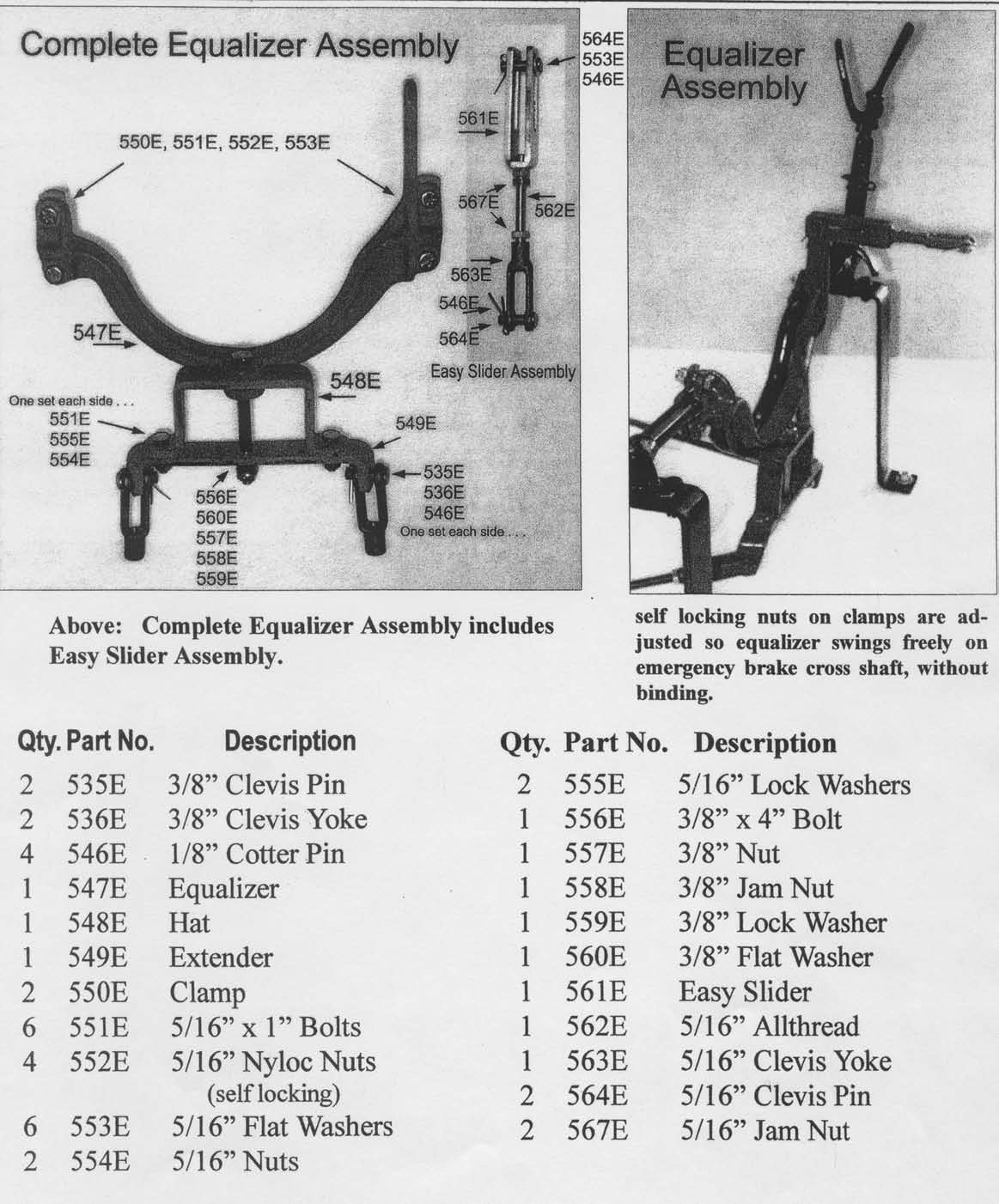
Equalizer assembly
New design sliding clevis attaches to the arm of the eouallzer.
Hang the equaliz- er in front of the parking brake cross shaft
so it just swings freely with the self- locking nuts. With the
bottom portion of the equalizer more inclined to the rear of the
car, adjust the pedal linkage so the pin in the sliding clevis
starts to move the equalizer arm. Hook the spring supplied to
the pedal and to the radius rod junction which is where the
radius rods meet on the drive shaft behind the uni- versal
joint.
Adjusting brake rods
Bending may be required on some models (note! Do not support
rods or bend near threads. Damage may occur) .adjust to take up
play between brake arms and equalizer. It is best to remove
stock rods while adjusting and then replacing. Check to see if
equalizer assembly hits oil pan with pressure applied. If so,
shorten rods. The following is to clarify the welding and
drilling of brake pedal.
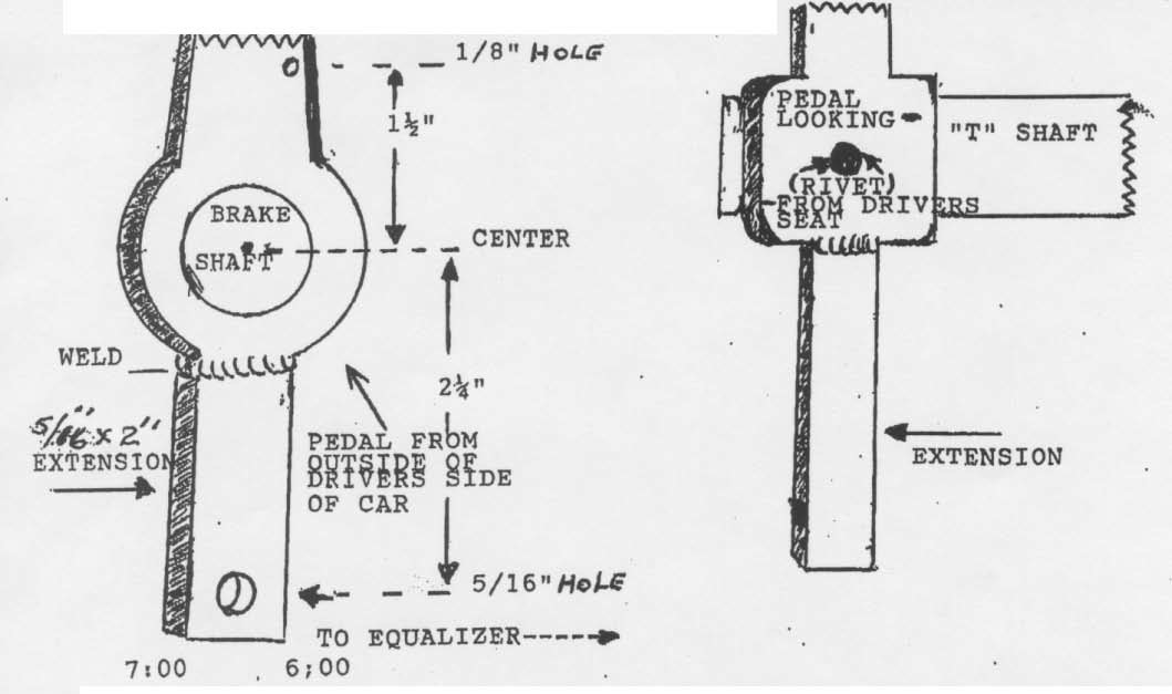
Measurements are from center of brake shaft. From center down to
extension
2 1/4? drill 5/16ths hole. From center up 1 1/2?, drill a-1/8th
hole near edge for pedal spring
Final notes: brakes do not self
energize in reverse as with some modern cars. Have you ever
backed up with the brake on only to find out to go forward the
emer- gency brake was on ? Also, large amounts of water will
cause brake fade on any brake system. Exercise caution under
these conditions. Riding pedal a short dis- tance helps return
braking.
Rocky mountain brake co ., inc. Assumes no responsibility for
the installation or use of rocky mountain brakes. There is no
expressed or implied warranty of fitness for a particular
purpose. Purchaser understands this product is intended for use
in addition to the standard original brake system.
Rocky Mountain Brake co., inc.
Additional information
Do?s and Don'ts
Our product is manufactured with the finest materials available.
With care, your new braking system will last many years. We
recommend the following maintenance procedures.
Do?s
Keep all mechanical moving parts lubricated. On the 1926-27 and
?t t?, clean brake drums of any paint , rust or any other
foreign matter. If you find your equal- izer yoke assembly hits
the engine pan, you have not made your adjustment of the
emergency brake correctly .bring lever back for the pawl to just
touch the clutch adjustment bolt. Brake pedal clevises can now
be adjusted with the foot pedal that is in it?s completely
seated position. Install brake rods to equalizer
And brake arms. Recommended clearance between lining and drums
is at least .020 (twenty thousandths), cold. A feeler gauge is a
good tool for this, if available. Remember heat expands drums
which means lining actually will become closer when hot .
Mechanical brakes, as in days of old, are susceptible to fade
out when large amounts of water are encountered. To overcome
this, ride brake pedal a short dis- tance to dry out .
For the first 100 miles, allow lining to ?break in? stopping
with slight pedal pres- sure. Burning them in will cause lining
to glaze and poor stopping will occur.
Don?ts
Don?t allow paint to be sprayed on lining or lining contact
surface of brake drums. Use masking tape to protect these areas
when painting. The small amount of primer on the 1909-25 drums
is insignificant. Don?t install your new brakes if your axle
seals show any sign of leakage. It is best to replace them at
this time.
Rocky Mountain Brakes:
A Step
By Step guide...
Written by R. Peterson
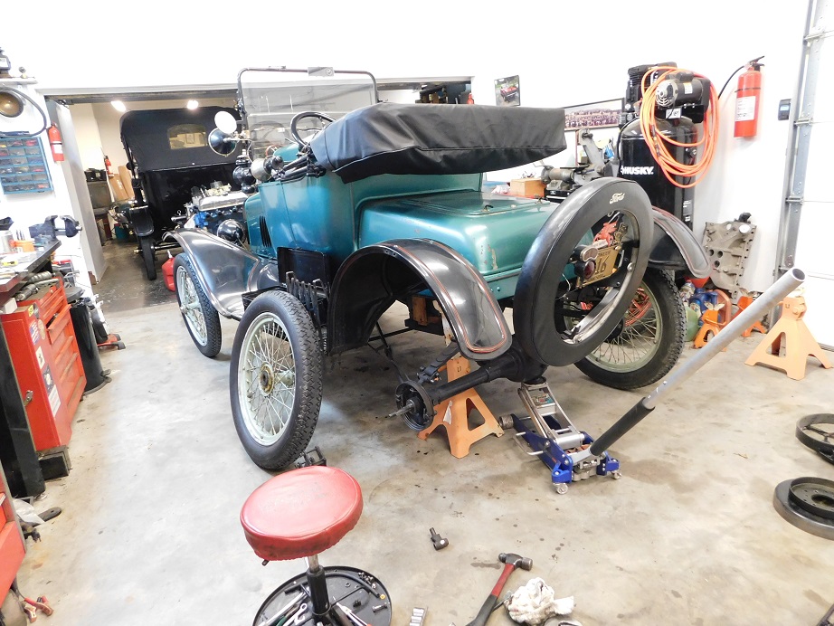
The car used in
the following demo is a 1917 torpedo runabout, a car that has
been in the family since it was purchased from the original
owner in 1951. The car gained a set of Hayes wire wheels in the
1950?s, and the Ruckstell axle was installed in the 1970?s. The
car has now been in the family for 66 years, and we want it to
be safe for future generations.
Before starting
the installation we painted all the parts black and read the
installation instructions carefully.
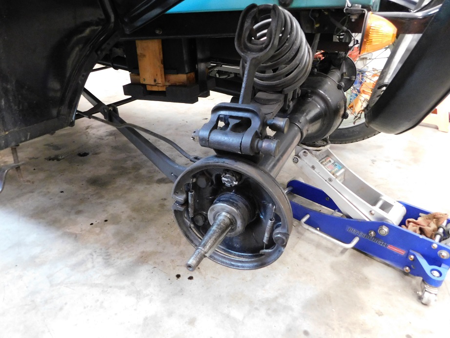
The first step is
to remove a rear wheel so that the brakes can be added. We
jacked the car up, installed a jack stand, and pulled the left
rear wheel. The Hassler shocks on the rear axle will not work
with the Rocky Mountain brakes so they will have to be removed.
The Hassler parts
removed, we can continue with installation.
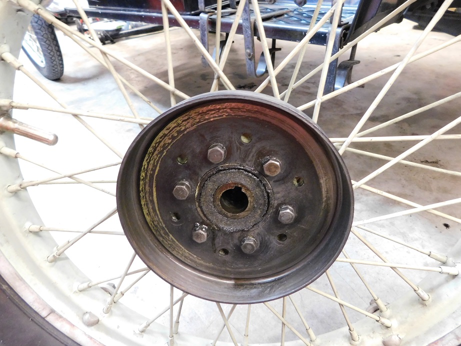
Our car has Hayes
wire wheels, a popular and attractive period accessory. The
Hayes rear hubs have a special, smaller diameter bolt pattern
holding the parking brake drum to the wheel. We will have to
drill the Rocky Mountain brake drums to match.
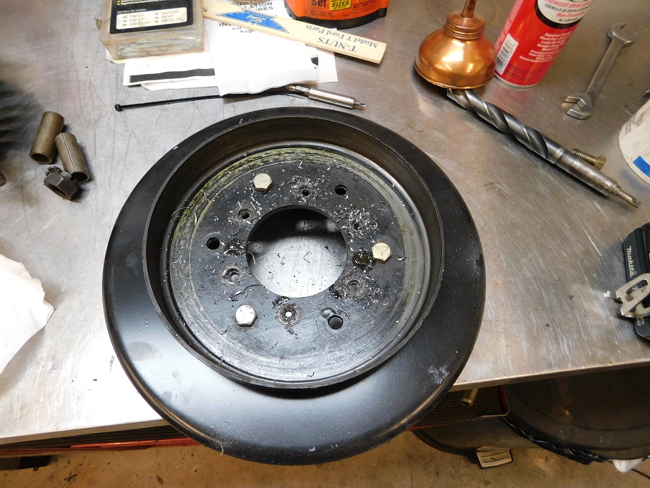
The Hayes brake
drum has both Ford and Hayes bolt patterns. This allows us to
bolt the Hayes drum to the Rocky Mountain brake drum to properly
align the two. We drill the six 3/8″ diameter holes on a drill
press using cutting oil and low speed. The Ford brake drum is
placed inside the Rocky Mountain brake drum. The bolts are
cleaned in MEK, dried, and then green semi permanent thread
locking Permatex compound is applied to the bolts before the
drums are secured to the wheel.
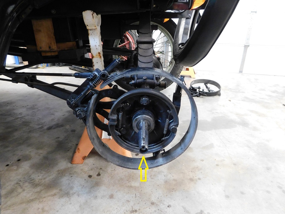
In the photo above
a yellow arrow points at an axle shim that is needed to
compensate for the additional thickness of the added Rocky
Mountain brake drum. The shim is .020″ thick, it moves the axle
.090″ out from center. The shims are not included in the RM
Brake kit, you must purchase them separately or fabricate them
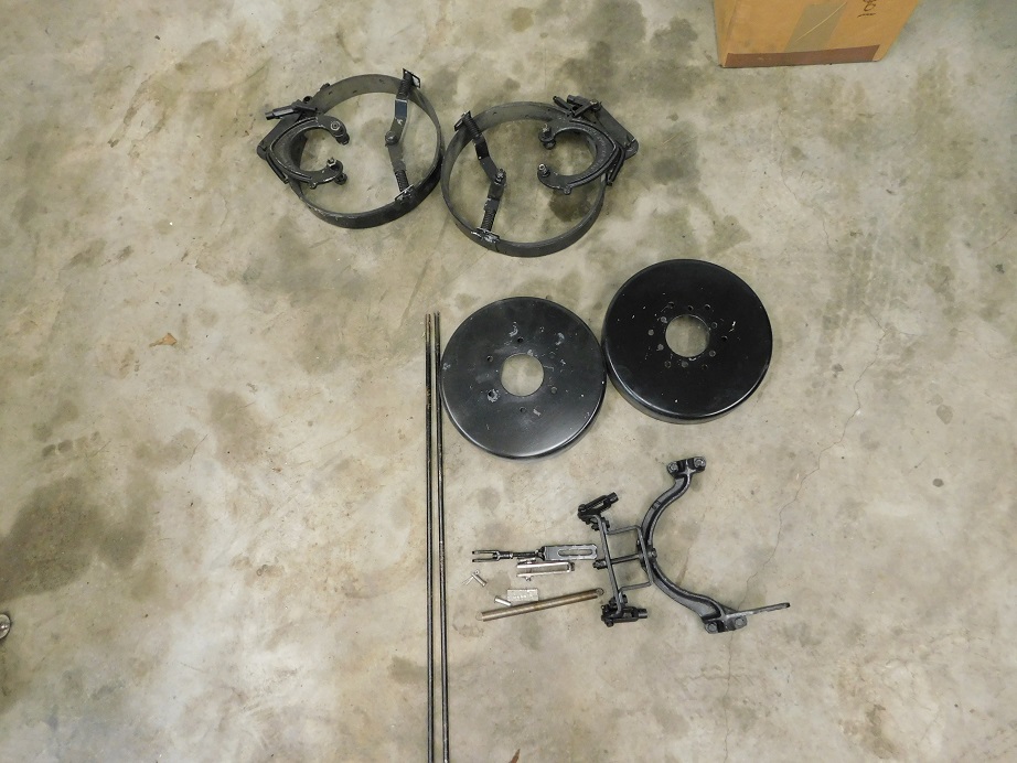
yourself. The Rocky Mountain brake parts are assembled per the
instructions using the new hardware supplied in the kit. The
rear wheels are installed and the axle nuts tightened and new
cotter pins installed.
Next we removed the floor boards and the transmission door so
that the brake pedal could be removed. Our 1917 had a starter
added, so the bendix cover had to be removed in order that the
brake pedal could be removed and replaced.
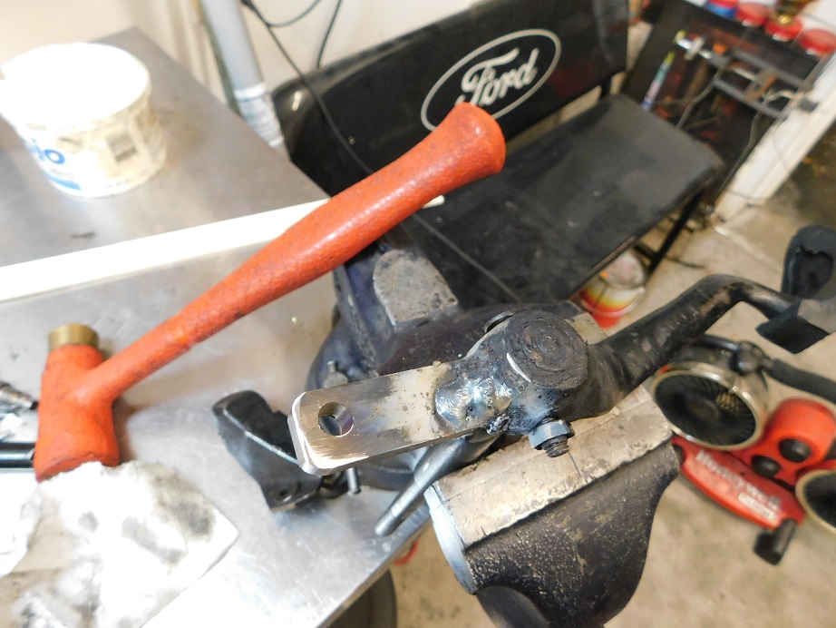
There is a piece
of steel plate included in the kit. You must drill a 5/16″ hole
in the plate to accept the brake clevis. The plate must be
beveled on the end to be welded in order to allow a larger
surface area for the weld, making it stronger.. A flat spot is
ground on the bottom of the pedal so the plate will have full
contact in the area to be welded. I took my pedal over to my
friend Nolan?s house. Nolan skillfully used his DC Arc welder to
put a nice fat bead on both sides of the plate.
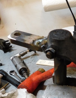
Another view of
the plate installed on the bottom of the pedal. The pedal
assembly can be painted if you wish, but given the environment
it lives in there is little reason to believe it would ever get
rusty.
The brake rods and clevis assemblies from the Rocky Mountain kit
were assembled. The equalizing assembly is installed on the
forward side of the Model T parking brake shaft. All the
clevises are hooked up with no cotter pins for now.
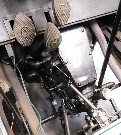
Above, an overview
of the installed brake pedal and equalizer with the brake lever
as far forward as it can go. It is important to properly adjust
the Ford parking brake before connecting the Rocky Mountain
Rods. The Ford parking brake lever when fully forward should
leave the brake cross shaft clutch arm just barely clear of the
clutch adjustment bolt. When the parking brake is applied with
the Rocky Mountain brakes disconnected the Ford brake lever
should be vertical, not all the way back against the seat.
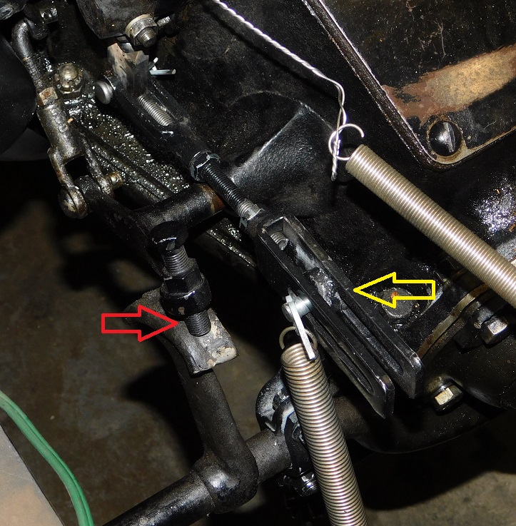
In the above photo
we see just a little clearance at the sliding clevis pin (yellow
arrow). The Ford brake pedal is adjusted so that when applied
the brake pedal is fully engaged and will stop the car with the
pedal about 1″ above the floor board. Test drive the car with
the Rocky Mountain brakes completely disconnected, make sure
that the Ford brake functions properly when going forward and
reverse. In this photo the parking brake lever is all the way
forward, note the (red arrow) clutch adjustment bolt just
clearing the brake cam.
Above, another
view showing the controls in the driving position with brakes
released.
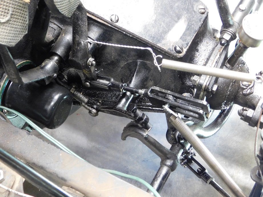
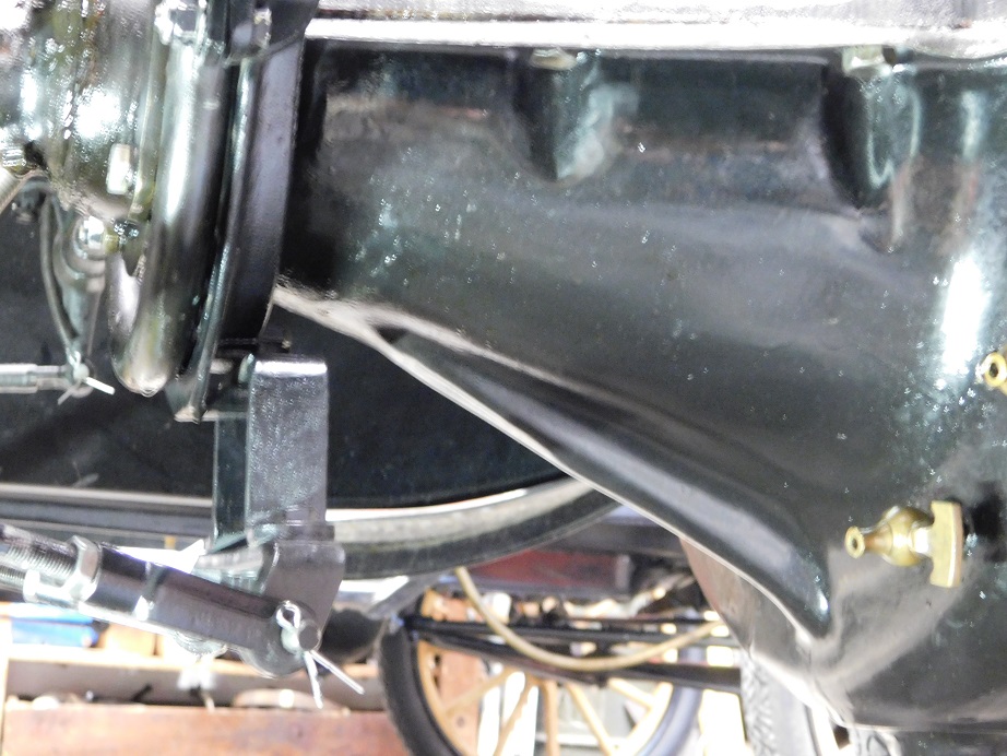
Above, the view of
the equalizer under the car with the brakes released and
properly adjusted.
Above, with the
brake lever applied the equalizer assembly is pushed forward by
the Ford brake lever shaft. It moves the brake rods
approximately 1/2" with everything adjusted properly.
Once you are happy with all of the brake adjustments double
check all of your work. Make sure all the bolts and nuts on the
brakes at the rear wheels are tight and install all the cotter
pins, but don?t bend them fully quite yet. Take the car on a
test drive for a few minutes. Make sure the car will stop while
backing up. Make sure the brakes hold well on a hill, going
backwards and forwards. Some additional fiddling and adjusting
will e necessary, I played with adjustments for nearly half a
day before becoming satisfied. When you feel that all is right
then get the car up to cruising speed, with no traffic around
and dry streets. Perform a few panic stops to see how it feels.
The car should stop without pulling to one side or the other.
One thing that I found after the first test drive was a
horrendous oil leak. When I removed the brake pedal I had
removed the starter bendix cover to get clearance. It was
removed again to try and figure out why we had such a big leak.
With it all apart again we were surprised to find the gasket
appeared to be perfect and no apparent problems. Everything was
cleaned with lacquer thinner and gasket sealant was used on the
next attempt. There were no leaks from the bendix cover after
that.
|