|
 Section A-B
Section C-D
Section E
Section F-H
Section A-B
Section C-D
Section E
Section F-H
Section I-O
Section P-R
Section S-T
Section U-Z
Back to Ford Model T Index
IGNITION KEYS
1913 - 1927
By Trent E. Boggess -
Plymouth State College, Plymouth, NH 03264
It seems that there is a story in even the simplest, most
common Model T part. For instance, take ignition switch keys. A key is a key,
right" Just make sure you have the right number. Well, maybe its not so simple.
From the time that the Ford Motor Company began using coils
and coil box assemblies of the K.W. Ignition " Ford
Motor Company design, the Company began to have a say in the design of the
switch keys. The first switch key was adopted for production on April 12, 1913
and was given the factory number T-5815. This key was actually an assembly of
three parts: T-5816, T-5817 and T-5823. The handle portion of the key was brass
plated. Keys were supplied by both the Clum Manufacturing Co. and the K.W.
Ignition Co.
The first real change in this key came on December 19, 1916.
The finish on the key was changed from brass plate to Raven Finish. Raven Finish
was a rust proofing process that was developed by the Ford Motor Company that
was very similar to Parkerizing. It left a black, phosphate coating on the
surface of the steel that tended to resist rusting.
On May 8, 1917, the key was redesigned. Instead of an
assembly of three pieces, the key was made from a single flat piece of
cold-rolled steel. The name of the key was changed as well. Instead of
"Switch Lever Assembly," this part became known as simply the
"Switch Key" This design was modified slighTLy on June 19, 1919 by
changing the inside corners of the "L" shaped plugs to have a
3/64" radius instead of a square corner to strengthen the dies which made
the key.
This key's factory number was changed to T-5815-A on February
13, 1919 to distinguish it from the key used on cars equipped with starters. It
remained a part of standard equipment until the use of the switch mounted on the
coil box of non-started equipped cars ended about August 9, 1922. Thereafter,
this switch key was given the designation T-5815-AR, the "R"
indicating that the part was to be used for repairs only. (Releases for
T-5815-AR)
The second type of key is distinguishable by the round shape
of the head of the key. It was a short lived design supplied by the Clum
Manufacturing Company. The tumbler notches appear on one edge of the key only.
According to factory records, it was used on the first 15,000 cars built with
electric starters in 1919. These cars were primarily sedans and coupes and had
the ignition switch and ammeter mounted on the instrument panel. Keys were
purchased by Ford in series numbers ranging from 1 to 32. Cars equipped with
starters came with two of these keys, as opposed to the non-starter cars which
came with only one T-5815-A. The Ford engineering records refer to this key as
T-5815-BR and it was given the name "Ignition Switch Key" to help
distinguish it from the earlier type. (Releases for T-5815-BR) The final and
most common key is characterized by a head that is diamond shaped. While it was
adopted on Feb. 21, 1919, the records suggest that this key was not used until
after April 23. This key was number T-5815-C. These keys were made out of nickel
silver and the heads were "pin frosted" on both sides. A smooth
1/8" by 3/8" surface was provided on the back side of the key for the
serial number of the key. These numbers ran from 51 to 74 inclusive. The front
face bore the word "Ford" in script.
These keys were made by a number of different vendors. On
December 19, 1919 Ford specified that the maker's trademark be placed under the
script "Ford" on the face of the key. Keys were supplied by five
vendors. These vendors and their trademarks are:
Cost cutting caused a change in these keys on Jan 16, 1920.
The "pin frosting" was eliminated and the front and rear faces of the
diamond head became smooth except for the borders, script word "Ford,"
trademark, and serial number boss.
The final change to the key came on January 30, 1926 when the
material the keys were made from was changed from nickel silver to "S"
brass. (Releases for T-5815-C)
INSTRUMENT PANEL
1909-1918
None used. Instruments, if any, were attached to the
dashboard (firewall). Accessory instrument boards were supplied by accessory
manufacturers, not by Ford.
1919
Boards were wood with "leather" covering in early
closed cars, and wood with metal covering later. Open cars, when equipped with
starter, used wooden panels initially. The ammeter was of large (about 2"
diameter glass) size and had a more elaborate movement than the later meters.
Initially, the ammeter had no script but early in the year "Ford Motor
Company" was specified. Then in about April, just "Ford" was used
on the face. The light switch handle was cast, and painted black. The meter and
switch were mounted on a rectangular panel which, in turn, was mounted on the
instrument panel.
1919-1922
Metal panel of near uniform width from side to side. The end
mounting ears were exposed and were fastened to the rear windshield post support
bolt. Instrument panels on open cars only when supplied with electrical
equipment. The ammeter was about the same size but of simple design. The switch
handle was now pressed steel. The handle, mounting board, and switch were all
black.
1922-1923
Metal panel now sloped slighTLy, with lower mounting bolts behind
the panel. The width tapers upwards at each side. Non-electric cars used a
blanking plate at the ammeter location.
1924-1925
Similar to 1923 but now had a support bracket for the steering column.
1926-1927
Metal panel built to appear more integral with the cowl. The
ammeter was smaller and mounted in an oval, nickel-plated escutcheon. The handle
on the light switch was nickel-plated on some of the later production, although
most seem to have been painted black. A dash lamp was an accessory supplied by
Ford (and others). The instrument panel was painted body color.
LAMPS
Note: Cars supplied with gas lamps were also supplied with gas generators, made by the same
firms that supplied the lamps. Generators were brass in the 1909-1912 era, then black and brass
in late 1912 through 1914. The generator was not necessarily the same brand as the lamps
on any one car. Some 1909 and 1910 (and probably later) cars were also supplied by the factory
with Prestolite tanks instead of the generator.
Pictures of items shown in blue can be seen by clicking
on them.
1909
|
HEADLAMPS |
|
E & J 466 |
Atwood CasTLe 84 |
Brown 15 (after about 10,000)
|
|
Variations in the
Atwood-Castle 84 |
|
SIDE LAMPS |
|
E & J "Pat. Pend." or "Pat.
1908" (early) |
E & J "Pat. Pend." or "Pat. 1908" |
Atwood Castle 204 |
|
|
Brown 60 |
|
TAIL LAMPS |
|
E & J "Pat. 1908" |
Atwood Castle 204 |
Brown 60 |
|
|
1910 |
|
HEADLAMPS |
|
E & J 466 |
Brown 15 |
|
SIDE LAMPS |
|
E & J "Pat. Pend." or
"Pat. 1908" |
Brown 60 |
|
TAIL LAMPS |
|
E & J "Pat. 1908" |
Brown 75 |
|
|
1911 |
|
HEADLAMPS |
|
E & J 666 |
Brown 19 |
|
SIDE LAMPS |
|
E & J "Pat. 1908" |
Brown 85 |
|
TAIL LAMPS |
|
E & J "Pat. 1908" |
Brown 78 or 75 |
|
The Brown 75 and 78 were similar. The 78 had a round clear lens on the side while the 75
had a rectangular clear lens on the side. The 78 is shown at the left. |
|
|
1912 |
|
HEADLAMPS |
|
E & J 666 with Ford script |
Brown 19 |
The Jno. Brown line in 1912 |
|
SIDE LAMPS |
|
E & J "Pat. 1908" |
Brown 100 |
|
TAIL LAMPS |
|
E & J "Pat. 1908" |
The Brown 105 was similar to the 115 except that it was all brass. |
|
|
1913 |
|
(Lamps were now steel, painted black, with
brass tops and rims.) |
|
HEADLAMPS |
|
E & J 666, 66 or 656 |
Brown 16 |
Victor |
|
E & J 66 |
Corcoran |
|
SIDE LAMPS |
|
E & J 30 or 32 |
Brown 110
No picture available but similar to the Brown 100 except for the
"black
and brass" design |
Victor |
|
Corcoran |
|
TAIL LAMPS |
|
E & J 10 or 12 |
Brown 115 |
Corcoran |
|
Victor (No photo available) |
|
|
1914 |
|
(Lamps were now steel, painted black, with
brass tops and rims.) |
|
HEADLAMPS |
|
E & J 656 |
Victor 2 |
Corcoran |
|
The E & J 666, 66, and 656 were alike. The model 66 had the
"66" off-center. It was
the "666" with the final "6" left out. |
The Victor and the Corcoran were almost identical. |
|
Brown Model 16
|
|
SIDE LAMPS |
|
E & J 32 |
Brown |
Victor |
|
Corcoran |
|
Lamps were the same as 1913 except for the side lamps with integral mounting
brackets as in the Brown. |
|
During later production side lamps were provided with
integral mounting brackets, eliminating the need for the separate brackets used
previously. |
|
TAIL LAMPS |
|
E & J 10 or 12 |
Brown 115 |
Corcoran |
|
Victor (No photo available) |
|
|
1915 |
|
HEADLAMPS |
|
(All lamps appeared alike, regardless of make. Early
production 1915 lamps varied; made by E & J, they had larger brass rims and
lenses (8-5/8 vs 8-1/8") than later standard style lamps. Lamps were supplied
by E & J, Brown, Victor and, perhaps others. Headlamp lenses were clear
glass until 1921.) Steel headlight rims specified in a letter dated June 19, 1915. |
|
6511X with large lens rim.
(E & J 456) |
|
6511X with brass lens
rim. (standard) |
|
Rim view |
Fork mounted |
Standard mount |
|
During the latter part of 1914 and perhaps early 1915,
headlamps were fork-mounted, on the same forks as used by the carbide lamps.
Early in 1915 the lamp with the riveted-in-place post became the standard. All
were electric, powered by the magneto with the bulbs wired in series. Brass rims
discontinued about June 1915. |
|
SIDE LAMPS |
|
6561X with large brass top
and lens rim. (E & J #6 on early cars) |
|
6561X with brass
top and lens rim. (standard) |
|
Interchangeable from side to side. Clear lens. Mounted from rear by
means of an integral stud. |
|
TAIL LAMPS |
|
6568X with brass top and
large lens rim. (E & J #7 early cars) |
|
6568X with brass top and
lens rim (standard) |
|
Similar in style to the side lamps, the large lens in the door was red,
with a small clear lens on the side facing the license plate. Mounted from the rear.
Side and tail lights were kerosene.
|
|
1916-1917
Head, Side, and Tail lights were now all painted black but continued the style of 1
915. |
|
Typical 1916-26 side light
|
Typical 1916-23 tail light
|
|
Identical to the later 1915 lamps except for the elimination of the brass
trimming. Painted all black.
|
|
1917-1919 |
|
HEADLAMPS |
|
6511BX |
|
In late 1917 a dimmer was added to the light switch on the magneto-powered
lamps. The lamps appeared the same as the 1916 style except for the use of bulbs with
two contacts (6-8 volt, 16 C.P.) instead of the older single contact type (8-9 volts,
18 C.P.).
|
|
1919-1920 |
|
HEADLAMPS |
|
6511CX |
|
Same appearance as the 1918 lamps but now provided with sockets for two
6-8 volt lamps on those cars supplied with electrical equipment. The main bulb was 6-8
volt, 16 C.P. and the "dim" bulb located in the upper part of the reflector
was 2-1/4 C.P. (the same bulb used in the tail light). Magneto lamps were dimmed
with a resistor or inductance and were the same as the 1918 type. |
|
SIDE LAMPS |
|
6561X |
|
Oil lamps the same as earlier but used only on non-electric cars. Starter
cars had no side lamps. |
|
TAIL LAMPS |
|
7669X (Electric) |
6568X (Oil) |
|
Electric lamp was small round type with large red lens and clear lens on the
side to illuminate the license plate. Used 2-1/4 C.P. single-contact bulb. Non-electric cars
used the oil tail lamp used earlier. |
|
|
1921-1923 |
|
HEADLAMPS |
|
Catalog photos of the green-
visored lens used for a short time in 1921 and the Ford "H" lens which
became standard shorTLy after. |
|
6511DX, 6511EX, and 6511HX (Battery)
6511KX (Magneto) |
|
The 6511DX used a frosted
"Tu-Lite" bulb with a clear lens. Early in
1921 the 6511DX clear lens was replaced with the 6511EX which had green "visor" and
used a clear "Tu-Lite" bulb. The "Tu-Lite" bulb was 6-8 volt, 18 and 2-3/4 C.P.
About June 1921 the 6511HX with the Ford "H" fluted lens became standard, and
continued through 1925 in the passenger cars. The 6511KX used in non-starter cars used a double
contact 6-8 volt, 21 C.P. bulb. The dimming inductance is mounted behind the area where the
ammeter would have been. |
|
SIDE and TAIL LAMPS
The same as 1
920 |
|
|
1923-1925 |
|
HEADLAMPS |
|
Same as 1923. Nickel-plated lens rims available as an option in late
1925 (before the 1926 models). |
|
SIDE LAMPS
Same as 1923. |
|
TAIL LAMPS
7669X (Electric)
8786CX (Electric in 1924 and later),
6568X (Oil) in early 1923
6568BX (Oil) about mid-1923 and later. |
|
The later oil tail lamp with the
small red lens at the rear and the large clear lens on the side facing the license
plate.
The revised tail lamp
which was mounted on the license bracket. It now consisted of a clear glass bowl
with a red disk at the rear, held in place by the outer shell which in turn was
held with a retaining spring to the license bracket. The lamp and bracket assembly
Was mounted on the spare tire carrier. |
|
Electric tail lamp changed to a similar style but mounted as an
integral part of the license plate bracket in 1924 (8786CX). This style continued
through 1927. The oil tail lamp, 6568BX, introduced in early 1923, was similar in
style to the earlier but now had the large lens facing the license plate, with a
small red lens on the side, facing the rear. This lamp had the mounting stud on the
side opposite the red lens. (It is possible that the earlier type tail light was
used as well, depending on the laws of certain states.) |
|
The Ford "H" lens used on
all headlamps until the end of Model T production in 1927. |
|
|
1926 |
|
HEADLAMPS |
|
Variations in headlamp mounting in 1926.
The first is on the left and the last is on the right. There were other variations
in the earlier tie-rod design as well. |
|
6501AX and 6502AX (Right and Left) magneto type. |
|
6501CX and 6502CX (Right and Left) battery type.
During 1926 production a bar was added between the front fenders, mainly to support
the front license plate. Note that the headlamps are not mounted on it, and the
variations in design of this bar.
|
|
The late 1926 and 1927
headlamps now mounted on the fender tie bar. Right and left designs were no longer
needed. |
|
6511NX magneto type, bar mount. |
|
6511MX battery type, bar mount. |
|
The 6501/6502 types were similar in shape to the 1925, but now mounted on posts
that in turn mounted on the fender. The right and left lamps differed mainly in the positioning
of the lens, and could be interchanged. Later 1926 production lamps (6511 M, N) were
mounted on the fender to fender tie rod. Standard lamps were all black but nickel-plated rims
were optional. Nickel became standard during the year. |
|
SIDE LAMPS
Oil lamps an
option on non-starter cars in early 1926 only (those built in 1925) and were the
same as the earlier lamps.
|
|
TAIL LAMPS
Same as the
1925 styles. A stop light combination became an option by March 1926. Oil tail lamp
used only on non-starter cars and was the same as the 1925 type.
|
|
The 1924-27 standard tail light assembly
|
The stop/tail light assembly |
|
|
1927 |
|
All lamps were the same as later 1926. All had nickel rims. No oil
lamps were used. |
MAGNETO
1909
(First 17,500 cars)
Magneto coil had double-stack round coils mounted on a pressed-steel ring. The ring had holes
of about the same diameter as the coils, located just inside the coils. The magnets were of
an elaborate forged design, 1/2" thick.
1909
(17,501-20,500)
Coil is similar to the earlier type but no longer has the
holes in the pressed-steel mounting ring. Magnets are similar to the earlier
type but now 9/16" thick.
1910-1914
At #20,501 The magneto was redesigned. The coil ring is now a
casting and again has the holes near the coils. The coils are still
double-stacked. The magnets are of the simple bent type and are now 5/8"
thick.
1914-1917
At #572,437 the magneto was again redesigned to accommodate
magnets of 3/4" thickness. The coils are now oval-shaped, still
double-stacked.
1917-1918
The coils are now single-stack but otherwise similar to the above.
1919-1923
Similar to the 1918 type but the ring now has a notch to clear the starter shaft.
1923-1927
Coil modified to now use 3/16" wide copper windings
instead of the 1/4" used earlier
MAGNETO POST
| |
|
|
"Brass" Magneto
Post (1909-1917)
3260 Magneto Contact Assembly)
Copyright 2002 Fun Projects, Inc. Edited and printed by permission. |
|
The very first Magneto Contact Assembly
used on the very early Ts was not the usual "Brass" post that is
normally found on the 1909-1917 cars. This very first assembly while
similar in concept had a short housing that was only 7/8" tall and
made entirely of hard fiber. It had a short small-diameter spring inside
that rested on top of the magneto primary contact of the magneto coil
ring. There was no slug in the end of the spring. This very first design
was drawn on September 21, 1908 but was soon replaced on November 25, 1908
with the more familiar "Brass" style. |
|
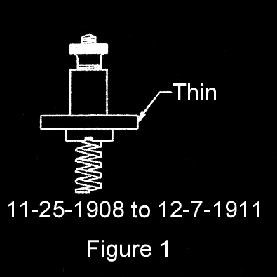
This first "Brass" design
featured a rather thin natural hard fiber ring (see Fig. 1) and the
internal special tapered spring (made from phosphor bronze) was designed
to fit tightly up in the brass sleeve while the other end simply sat on
the primary magneto contact as did the earliest design. The internal brass
sleeve was crimped in two places at the bottom in a groove placed there
for that purpose. The assembly was held in place with three 10-32 x
3/8" Fillister-head machine screws. |
|
 |
 |
|
No lock washers were used. A brass thumb nut with a
diamond knurl pattern was used to fasten the magneto wire and a small
3/8" OD lock washer was used there.
The gasket used between the post and the transmission cover
was made of felt.
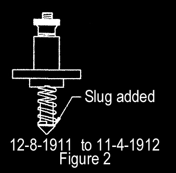
December 8, 1911 a brass pointed slug was added inside the
spring end. (see Fig. 2) The remaining design was not altered. The design
used through November 1912 was somewhat frail and easily broken. There are
very few surviving pieces of this original design.
May 20, 1912 the length of the 10-32 Fillister head mounting
screws was increased to 1/2".
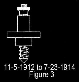
November 5, 1912 the height of the magneto post hard fiber
ring (and the internal brass inserted sleeve) was increased by 1/4"
overall and the crimping slot at the bottom was removed. The screw ring
portion was increased in height by 1/16" while the part below the
mounting ring portion was increased by 3/16".(see Fig. 3) The sleeve
was now crimped in four places but there were no grooves placed for the
crimps. The crimping action merely increased the diameter at the end of
the sleeve. |
|
 |
 |
|
December 18, 1912 the material used for
the slug in the end of the spring was changed from brass to steel. This
change was a bad idea since the dissimilar metals (bronze and steel) being
in contact would result in galvanic corrosion due to electrolysis. The
design was changed again before this problem probably came to light. A
note on the print at this time said that for hard gray natural fiber
material a vendor could use scrap from the commutator fiber block (which
was not typically made from hard fiber but from a phenolic (paper based)
material.
Many original-looking magneto posts from early cars show a
red colored material (probably phenolic). The design of these units also
appears to be the later (after 1914) design leading to the natural
conclusion that the earlier post broke and was replaced.
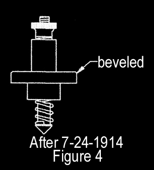
July 24, 1914 a bevel was added around the top perimeter of
the fiber screw mounting ring (see Fig. 4).
August 22, 1914 the mounting gasket material was changed to
cork with thickness specified as 1/16-5/64".
February 22, 1915 the gasket material changed to imitation
leather, quality M, which is the material out of which seat backs and
cushions were made. The drawing said the gasket was to be made out of
scrap from these parts.
June 19, 1916 the drawing was again changed to show the use
of two gaskets per car as a double thickness.
December 30,1916 the spring material was changed to zinc
plated steel.
March 21, 1918 the gasket material was changed back to 1/16-
5/64" thick cork and the quantity per car back to one.
May 10, 1919 a note was added to the drawing stating to
"Cement to block with Silicate of Soda".
May 13, 1919 the gasket thickness was changed to
3/64-5/64" and a note was added to read "Make from center of
T-1764" (which was the starter Bendix cover gasket).
August 19, 1919 the gasket material was again changed to a
1/32" thick "treated fiber sheet; packing, oil, water, gasoline
and air proof, guaranteed to a temperature of 300 degrees F."
June 8, 1920 the gasket material was changed back to
3/64-5/64" thick cork again which remained the material used for the
rest of Model T production.
December 22, 1924, there was one final change to the
thickness of the cork when the thickness was changed to 1/16-5/64".
April 16, 1926 a notation was added to the drawing to
"Refer to M-6024 for material specifications."
Note:
About 1917-18 a metal retaining "shell," P/N 3267C
(T-8611), was added. This shell fitted over the contact assembly like a
cup washer and prevented the retaining screws from deforming the
insulation, which was then made of "Fordite," a plastic-like
material and was P/N 3267B (T-1503B). This continued until the
"Improved Fords" appeared, in the summer of 1925, at which time
the contact assembly 3260B (T1545B) became somewhat like a spark plug and
screwed into the transmission cover using 1/2-inch pipe threads. |
MANIFOLDS
1909-1911
Intake manifold was "dog-legged" aluminum. Exhaust pipe
fitted into the exhaust manifold and had asbestos packing, secured with usual nut.
1911-1913
Intake manifold changed to straighter aluminum type. Exhaust manifold was the same as 1910 type.
1913-1914
Intake was the same pattern as 1912 but was now made of cast iron (as per
letter dated December 19, 1912). In January 1913 another letter specified the
exhaust manifold was made for the flanged exhaust pipe. This new design exhaust
manifold remained standard until late 1926.
1914-1926
Same as 1914 type. The 1915 sedan which had the fuel tank
under the rear seat used a longer intake manifold (which lowered the carburetor)
for better fuel flow to the carburetor.
1926-1927
Vaporizer carburetor with integral manifolds, used in some production in 1925 and 1926 became
standard in late 1926.
MUFFLER
1909-1910
(The first 2500 cars were somewhat different from the
production version.)
Cast-iron end plates. Mounted with sheet metal brackets.
Straight, longer tail pipe. Asbestos wrapping secured with three iron bands. The
two ends were retained with three long rods threaded at both ends.
1911-1914
Similar to 1910 but tail pipe tapered and curved downward.
The retaining rods were changed to have a hexagon head on one end. The asbestos
wrap was dyed black.
1914-1916
Cast end plates now have integral mounting brackets. Pipe is
now straight and not tapered. Mounting brackets are longer than the 1917 type.
The asbestos was no longer dyed black.
1917
Similar to 1916, with and without tail pipe. No asbestos
wrap, painted with F-140 paint. Shorter cast mounting brackets. Only one long
retaining rod to hold the ends together.
1918-1920
Same as 1917 but no tail pipe. In June 1919 the outlet was
moved 10 degrees from the bottom to direct the exhaust away from the spare tire.
"Ford" in script added to the end plates during 1919.
1920-1927
Pressed-metal design. No tail pipe.
MUFFLER PARTS
|
Part # |
Factory # |
Description |
|
MUFFLER COMPLETE
1909-1920 |
|
4025 |
1200B |
|
1921-1927 |
|
4025B |
1200C |
FRONT HEAD
1909 |
|
4026 |
1202 |
Early 1909 |
|
1909-1914 |
|
4026 |
1202B |
Steel mounting brackets |
|
1914-1920 |
|
4026B |
1202C |
Integral mounting bracket. Cast bracket is long thin casting 1914-1917.
1917-20 has a short, stubby casting. |
|
1921-1927 |
|
4026C |
1202D |
Pressed steel, no mounting bracket. |
REAR HEAD
1909 |
|
----- |
1201 |
Separate tail pipe, F/N 1213 |
|
1909-1910 |
|
4040 |
1221 |
Steel brackets, straight pipe. |
|
1911-1914 |
|
4040 |
1221 |
Steel brackets, curved pipe |
|
1914-1917 |
|
4040 |
1221B |
Integral bracket, straight pipe with no taper. |
|
1917-1920 |
|
4040B |
1201D |
Integral bracket, no pipe. Shorter mounting bracket. |
|
In June 1919 the exhaust opening was moved ten degrees to
direct exhaust away from the spare tire. |
|
1921-1926 |
|
4040C |
1201E |
Pressed steel, no pipe. Integral mounting bracket was
on the rear cap only. |
|
1926-1927 |
|
4040D |
1209 |
OUTER SHELL
1909-1927 |
|
4027 |
1203 |
5 x 12" |
MIDDLE SHELL
1909-1927 |
|
4028 |
1204 |
(3-1/2 x 13") |
INNER SHELL
1909-1927 |
|
4029 |
1205 |
2 x 14" |
TIE ROD
1909-1917 |
|
4030 |
1206 |
5/16 x 13-3/8" |
|
1917-1920 |
|
4030B |
1206B |
REAR BRACKET
1909 |
|
----- |
1208 |
(Early 1909) |
|
1909-1914 |
|
4032 |
1217 |
FRONT BRACKET
1909 |
|
----- |
1209 |
(Early 1909) |
|
1909-1914 |
|
4033 |
1218 |
EXHAUST PIPE
1909-1913 |
|
4037 |
1214 |
Non-flared, engine to muffler |
|
1913-1920 |
|
4037B |
1214 |
Flared at end to fit manifold |
|
1920-1927 |
|
4037C |
1214B |
For pressed steel muffler. Longer and punched for muffler retaining
cross piece at rear. |
ASBESTOS WRAP
1909-1915 |
|
4038 |
1215 |
1/32 x 12-1/4 x 31-3/4" |
MUFFLER BANDS
1909-1915 |
|
4039 |
1216 |
1/32 x 3/4 x 18" steel. These were the same bands that were
used for heating ducts in buildings. They had a loop at one end through which the
other end was threaded, then folded over. |
MUFFLER MODIFICATION DATES
Note: These dates are the dates the changes
were made in the releases and/or blueprints, and are not necessarily the dates the
change appeared in production.
|
Factory # |
Date |
Part Name |
Notes |
|
T-1206-A |
02-14-08 |
Rod |
Adopted |
|
T-1201-A |
02-12-08 |
Head (Exp.) |
Adopted for first 2500. |
|
T-1203 |
02-13-08 |
Outer Shell |
Adopted. |
|
T-1202-A |
02-14-08 |
Head (front) |
Adopted for first 2500. |
|
T-1213-A |
02-14-08 |
Pipe |
Adopted for first 2500. |
|
T-1200-A |
03-06-08 |
Muffler Assy. |
Adopted for first 2500. Obsolete on 3-21-13. |
|
T-1215 |
10-29-08 |
Asbestos |
Adopted. (1/32" thick) |
|
The first 350 landaulets were different from the above, Using different heads
and brackets. |
|
T-1201-B |
12-08-08 |
Head (rear) |
Adopted. Obsolete on 11-21-13. |
|
T-1213-B |
12-08-08 |
Pipe |
Adopted |
|
T-1200-B |
12-10-08 |
Muffler Assy. |
Adopted |
|
T-1222 |
04-16-09 |
Asbestos |
Adopted for use on T1200B. |
|
T-1202-B |
04-23-09 |
Head (front) |
Adopted |
|
T-1201-C |
04-24-09 |
Head (rear) |
Adopted. |
|
T-1200-B |
09/14/09 |
Muffler Assy. |
Change in Muffler bracket. Exhaust T-1217 &
Intake T-1218 |
|
T-1213-B |
10-06-10 |
Muffler Pipe |
Changed and redesigned to be tapered and curved. |
|
T-1213-B |
01-23-11 |
Pipe |
Changed angle of pipe from 36 degrees to 18 degrees. |
|
T-1202-B |
06-09-11 |
Head (front) |
Changed from malleable iron to pressed steel. |
|
T-1206-A |
06-29-11 |
Rod |
Removed threads from one end and added 1/2" hex head. |
|
T-1202-B |
08-04-11 |
Head (front) |
Changed from pressed steel to Malleable Iron. |
|
T-1202-B |
09-25-12 |
Head (front) |
Change bolt circle radius from 2-1/4" to 2-3/16". |
|
T-1215 |
10-11-12 |
Asbestos |
Specified to be dyed black |
|
T-1203 |
10-29-12 |
Shell (outer) |
Changed material from sheet steel to black sheet steel. |
|
T-1201-C |
02-24-13 |
Head (rear) |
Added bracket for attaching muffler heads to the frame. |
|
T-1203 |
03-04-13 |
Shell (outer) |
Specified shell to be spot welded together in six
places instead of riveted. |
|
T-1203 |
07-25-13 |
Shell (outer) |
Specified shell to be spot welded together in
five places instead of six. |
|
T-1215 |
08-28-13 |
Asbestos |
Removed note specifying this asbestos to be dyed black. |
|
T-1213-B |
11-08-13 |
Pipe |
Specified pipe to be straight instead of bent. |
|
T-1201-C |
03-03-14 |
Head (rear) |
Specified the bracket for holding muffler head
to frame be stright instead of curved for ease in assembly |
|
T-1202-B |
04-03-14 |
Head (front) |
Specified bracket holding head to frame to be
straight instead of curved. |
|
T-1201-C |
12-21-15 |
Head (rear) |
Added V-shaped locking boss to prevent muffler
rod from turning around while assembling. |
|
T-1201-C |
09-25-16 |
Head (rear) |
Changed bolt circle radius from 2-1/4" to
2-3/16". |
|
T-1202-B |
12-09-16 |
Head (front) |
Changed material from malleable iron to cast iron. |
|
T-1201-C |
12-09-16 |
Head (rear) |
Redesigned, changing material from
malleable iron to cast iron. |
|
T-1215 |
12-18-16 |
Asbestos |
Obsolete. Asbestos on hand to be placed in stock and used
where it can be used to the best advantage. |
|
T-1206-B |
04-06-17 |
Rod |
New design for single-bolt muffler. |
|
T-1201-C |
04/06/17 |
Head (rear) |
Experimental manufacture. To be run at rate of
100 per day. Parts to be held together with one bolt instead of three. |
|
T-1201-D |
04-16-17 |
Head (rear) |
Exp. manufacture design |
|
Note: T-1201C experimental became T-1201-D when they began production. |
|
T-1202-C |
04-16-17 |
Head (front) |
Experimental manufacture. Used one bolt instead of
three. |
|
T-1202-B |
09-28-17 |
Head (front) |
Specified for repairs only. |
|
T-1201-C |
09-28-17 |
Head (rear) |
Added note for repairs only |
|
T-1202-C |
09-28-17 |
Head (front) |
Adopted for regular production. |
|
T-1213-B |
09-28-17 |
Pipe |
Specified to be used for repairs only. |
|
T-1201-D |
09-28-17 |
Head (rear) |
Adopted for regular production. |
|
T-1202-C |
03-19-19 |
Head (front) |
Specified name Ford in script to be cast in. |
|
T-1201-C |
03-19-19 |
Head (rear) |
Specified Ford script to be incorporated in part. |
|
T-1201-D |
03-19-19 |
Head (rear) |
Specified Ford script to be incorporated in part. |
|
T-1206-B |
04-29-19 |
Muffler Rod |
Changed head from hex to 5/16" wide by 11/16" long |
|
T-1201-D |
06-07-19 |
Head (rear) |
Redesigned outlet to deflect exhaust away from
spare tire carrier. |
|
T-1203 |
12-16-19 |
Shell (outer) |
Specified shell to be spot welded together in ten places. |
|
T-1201-D |
01-08-20 |
Head (rear) |
Redesigned reinforcing rib which supports foot making
it heavier. |
|
T-1206-A |
02-05-20 |
Rod |
Changed head from hex to 5/16" wide by 11/16" long. |
|
T-1202-D |
04-23-20 |
Head (front) |
New Pressed steel design. To be run at rate of 500
per day. |
|
T-1200-C |
04-23-20 |
Muffler Assy. |
New number, new design (Pressed steel ends) |
|
T-1200-C |
08-13-20 |
Muffler Assy. |
Ends to be made out of two thicknesses of fender
scrap instead of one thickness of stock. |
|
T-1201-C |
09-13-20 |
Head (rear) |
Obsolete. |
|
T-1201-E |
09-23-20 |
Head (rear) |
New pressed steel design. For experimental manufacture. |
|
T-1206-B |
10-11-20 |
Rod |
Specified for repairs only. |
|
T-1202-D |
10-11-20 |
Head (front) |
Adopted for regular production. |
|
T-1200-C |
10-11-20 |
Muffler Assy. |
Adopted for regular production |
|
T-1200-B |
10-11-20 |
Muffler Assy. |
Use for repairs only. |
|
T-1202-C |
10-11-20 |
Head (front) |
Specified for repairs only. |
|
T-1201-D |
10-11-20 |
Head (rear) |
For repairs only. Replaced by pressed steel design. |
|
T-1201-E |
10-11-20 |
Head (rear) |
Adopted for regular production. |
|
T-1201-E |
11-19-20 |
Head (rear) |
Changed opening for exhaust head |
|
T-1200-D |
01-08-24 |
Muffler Assy. |
Adopted, new number, new design. |
|
T-1200-C |
01-08-24 |
Muffler Assy. |
Suffix
"R" added to symbol # as same
will not be used with hot air stove. |
|
T-1201-F |
02-09-24 |
Head (rear) |
Adopted |
|
T-1201-F |
11-28-24 |
Head (rear) |
|
T-1200-C |
11-28-24 |
Muffler Assy. |
Removed R from symbol number and specified for
use in 1924. |
|
T-1200-D |
11-28-24 |
Muffler Assy. |
Obsolete. |
|
T-1203 |
03-26-25 |
Shell (outer) |
Specified shell to be spot welded together in four
places instead of five. |
|
T-1200-C |
05-05-25 |
Muffler Assy. |
Specified bracket to be integral and upper flange
to be spot welded in four places to keep metal from shifting when forming. |
|
T-1201-E |
05-05-25 |
Head (rear) |
Obsolete. |
|
Note: There was another change in the muffler rear head.
The drawings dated 5-16-26 for the muffler assembly show a different exhaust
head. The outlet hole has been moved 180 degrees and is located at 4 o'clock
instead of 11 o'clock and instead of an oval hole, the metal is pierced on three
sides and a hinge is left causing the remaining flap to serve to deflect the
exhaust. |
OILERS
(Front axle tie rods, etc.)
|
11-20-07 |
T218 screw-in brass oiler adopted. |
|
07-11-11 |
T283 steering spindle connecting rod oiler, two required |
|
11-19-12 |
Design changed from Bowen 4-N to Zerk oilers. |
|
03-07-13 |
Changed back to Bowen 4-N design. |
|
01-08-14 |
Drawing changed to note that the same oiler was being used for T267 front and
rear spring hangers and T283 spindle connecting rod oilers. |
|
07-24-14 |
Spindle bolt redesigned to incorporate a built-in oiler |
|
07-16-15 |
Spring hangers redesigned with an oiler in the perch and in the lower hanger. |
|
07-11-16 |
Oilers removed from the hangers and press-in oilers added to the perches.
(There was considerable overlap in production with combinations of old and new types being used.) |
|
09-06-16 |
"Brought drawing up to date with oilers as they are being made by changing
the design from 4N Bowen. The new type was the Winkley. |
|
09-30-16 |
T2944 spring oilers. These were used on the springs, replacing the hanger oilers.
They were Winkley 1-G "Special Winkley Oiler." They appear to have a spring-loaded ball
as a "door." Push the ball down to add the oil and then the ball seals the hole. They
were zinc plated. |
|
11-29-16 |
Changed from the above Winkley to the man-hole style, also made by Winkley, and
were initially raven finished but later Zinc coated. This oiler was also used on the
commutator. |
|
12-13-16 |
Changed to Winkley oiler #3, Style R. |
|
02-08-17 |
This same oiler now used on the spindle bolts. |
|
03-15-18 |
No longer used on the commutator. |
|
07-03-19 |
A larger oiler was now used on the spindle bolts. |
|
08-07-19 |
This larger oiler was also used on the tie rod bolts. |
|
04-03-22 |
T2944-A3
"flip top" oiler now specified. These were made by Bowen and
were zinc plated, and were used until the end of Model T production. |
OIL FILLER CAPS
Early 1909
Apparently there was no "standard"
cap used on the early (first 2500) engines on which the
oil filler pipe was located at the front left of the
engine. Several types have been observed but apparently
no one is certain which is correct. In general, though,
all had a cup-like funnel at the top of the filler tube.
These early filler pipes had a screen over the funnel
which also supported the cap but due to this
construction the screen was easily torn leaving no way
to hold the cap.
1909-1912
Now located at the right-front of the engine. A thin brass
"pipe" with a screen at the top, which fitted into the oil filler
spout.
1912
Brass cap with "Ford" with six flutes (notches) around the top.
1912-1914
Brass. Similar to the earlier but
"Made in USA"
added. The style of the "Ford" and of the "Made in USA"
varied, perhaps because of different suppliers.
1914-1915
>Steel with Ford script, in the same pattern as the earlier
type. The "Made in USA" did not appear on all caps.
1915-1927
Steel, with script until 1916 and without script from then
on. Simpler design, somewhat larger, and with just three flutes around the top.
DOCUMENTATION
(From factory drawings. The dates are those of the drawings, not necessarily the dates of production.)
|
T582B Oil breather pipe |
|
1/21/09 |
New drawing |
|
1/19/09 |
To be used after first 2500 cars |
|
3/4/09 |
To be made of flat rolled steel instead of brass tubing. Two pieces of gause used
inside. |
|
3/10/10 |
New design to go into effect immediately |
|
5/16/10 |
Obsoleted new design and reinstated old design |
|
6/5/10 |
New design (not indicated) |
|
6/21/11 |
Changed width of slot from 1/16 to 1/8" (This filler pipe did not have a
cap. The end was open with just a screen to keep out dust and dirt.) |
|
11/22/11 |
New drawing |
|
T4468 Oil breather pipe and cap assembly
(T582B and T509) |
|
2/9/12 |
Cap soldered in place in two places |
|
8/31/12 |
Made in USA to be stamped in cap |
|
1/21/14 |
Specified cap to be soldered in three places |
|
2/24/14 |
Changed material from sheet brass #22 B&S .025 to cold rolled steel
#22 US .031 (fender scrap |
|
2/26/14 |
Cap not spot welded to pipe in three places |
|
4/25/14 |
Now welded in two places. Brought up to date incorporating certain changes in
T5090 (509C") |
|
8/24/14 |
Changed distance between the pockets on inside of cap from 1-1/2 to 1-1/2 to
1-33/64" |
|
12/10/14 |
Called for six lugs on the bottom which are to be clinched over the rib which
holds the gause in place in the breather pipe, holding the cap to the pipe. |
|
4/23/15 |
Changed inside diameter from 2" to 2-3/16" and the number of pockets
and lugs from 6 to 3. Changed height from 3/4 to 13/16, specifying bottom of pockets to be connected
with the top of the cap by a 1/4" radius of the inside of cap. |
|
8/16/15 |
Changed material from fender scrap to running board shield or fender apron scrap. |
|
5/5/16 |
Removed the name
"Ford" and the "Made in USA" |
For the first 2500 cars the cap was a malleable iron cap that looks about
like the one on Model NRS cars. That was factory number T-510.
The first breather pipe design for the thermo-siphon engine
was adopted on Dec. 8, 1908. This was a design which consisted of a brass
cylinder. The top quarter inch was of larger diameter than the hole in the front
timing cover for the breather pipe, and inside the tube were three layers of
brass gauze. The top quarter inch was also knurled to provide a grip for getting
the pipe out. The factory drawing, though, was clearly labeled "never used."
The second design, T-582-B, was adopted on January 21, 1909.
The tube was made out of brass, had a piece of brass gauze inserted, but no cap.
This would be real easy to make; take a later brass oil filler cap assembly and
take off the cap.
On March 10, 1910 a new design was adopted to replace the old
one. Same factory number but a different design. A month an a half later, on May
16, 1910, the new design was obsoleted and the old design reinstated. The brass
gauze in this one is held in place not by a ring turned into the tube, but by
little tabs stamped out of the tube.
The cap for the breather pipe was not adopted until November
22, 1911. It was made from brass and had Ford in script embossed into the top.
It was made by Keim in Buffalo.
On August 31, 1912
"Made in USA" was added under
the name Ford. The "Made in USA" was stamped into the cap while
the "Ford" continued to be embossed.
On February 24, 1914 the material for making the cap changed
from sheet brass to cold rolled steel " fender
scrap.
The big change came on April 23, 1915. The diameter increased
from 2" to 2-3/16" and the number of lugs decreased from six to three.
The releases indicate that the old style was to remain in production until the
new dies could be made. Note that the Name FORD and the Made in USA remained on
the top of this cap. These are bona fide Ford caps, not spurious.
On August 16, 1915 the material was changed to a thicker
heavier gauge of steel. Here after the caps would be made from running board
scrap, not fender scrap.
On May 5, 1916 the embossed
"Ford" and the stamped
"Made in USA" were removed from the cap. Thereafter the cap remained
unchanged until the end of Model T production.
|